Лазерный дальномер или датчик расстояния, измеряющий время пролета света от устройства до объекта и обратно (ToF Lidar)
все эксперименты ночью и в безлюдной местности. Оказывается могут обвинить по хулиганству с опасными вещами (вз р в чаткой) и отправить на Колыму на экскурсию лет на 5.
«Реального гранатомёта у нас не было». Режиссёр роликов про Виталия Наливкина рассказал об уголовном деле
Secretmag.ru 1 час назад Полицейские задержали депутата Николая Бондаренко Как научиться слушать себя и стоит ли доверять интуиции 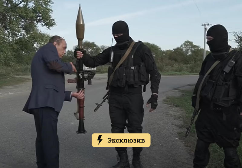
На авторов проекта BARAKuda, который выпускает интернет-сериал про вымышленного депутата Виталия Наливкина, возбудили уголовное дело о хулиганстве с применением взрывчатки. Причиной стал ролик, на котором главный герой стреляет из гранатомёта по билборду «Единой России». Режиссёр сериала Андрей Клочков заявил «Секрету», что агитационный щит разнесли с помощью киношной пиротехники в безлюдном месте. Поначалу никаких претензий к создателям видео не было, но позже мэрия Уссурийска пожаловалась на них в полицию.
Ролик «Виталий Наливкин предотвратил теракт» появился на YouTube-канале проекта BARAKuda 20 сентября. На нём вымышленный председатель исполнительного комитета Уссурийского района Виталий Наливкин выстрелом из гранатомёта случайно уничтожает агитационный билборд партии «Единая Россия».
Режиссёр ролика Андрей Клочков в беседе с «Секретом» сообщил, что после съёмок никаких претензий со стороны властей к создателям видео не было. По его словам, по указанию полиции на место приехали сотрудники МЧС. Специалисты осмотрели место «взрыва» и заключили, что «никакого ущерба даже близко не было».
«Реального гранатомёта у нас не было. Мы пиротехнику использовали, а сам гранатомёт — это макет, который есть в свободной продаже. Выстрел и взрыв пиротехнической петарды снимали отдельно, за городом, в безлюдном месте, с соблюдением всех мер предосторожности. После съёмок мы привели всё в первозданный вид», — сказал Клочков.
Тем не менее через полтора месяца после записи ролика на съёмочную группу BARAKuda возбудили уголовное дело о хулиганстве с применением взрывчатых веществ. Наказание по этой статье предусматривает лишение свободы на срок от 5 до 8 лет. Клочков уточнил, что фигурантами стали три человека — он сам, оператор-монтажёр Александр Анисимов и продюсер проекта Семён Вавилов.
По словам Клочкова, несмотря на заключение МЧС об отсутствии какого-либо ущерба инфраструктуре после съёмок, через полтора месяца после записи ролика администрация Уссурийска предъявила претензии авторам интернет-сериала.
«За этот эпизод решили зацепиться. Сразу возникло заявление от администрации города, что якобы есть какой-то ущерб на 32 000 рублей. И на основании этого заявления на нас возбудили уголовное дело. Нас сначала лицом в пол положили ОМОНовцы, когда залетали к нам на творческую студию, а потом нам просто зачитали постановление о возбуждении дела», — рассказал режиссёр BARAKuda.
Сейчас силовики проводят обыски на студии, допрашивают свидетелей. Клочков отметил, что у обвиняемых пока нет адвокатов, создатели интернет-сериала рассчитывают на поддержку общественности.
Проблемы с законом у BARAKuda возникли не в первый раз. В сентябре суд Уссурийска арестовал 43-летнюю Ларису Кривоносову, которая исполнила роль сотрудницы полиции Марины Вульф. Зрители увидели в ролике пародию на официального представителя МВД России Ирину Волк. В октябре женщину приговорили к трём месяцам колонии за неоднократное нарушении правил административного надзора, который был установлен за ней в 2017 году.
Фото: youtube.com
Читайте также:Российскому блогеру грозит дело из-за шуточных видео о депутате. По сюжету он борется с коррупцией
Ролик стендапера помог следствию выйти на московского лжериелтора
Блогера Юрия Хованского арестовали по делу об оправдании терроризма
Россиянин потребовал от группы Metallica $1 млрд и пожизненное содержание
Безос проиграл в суде Маску. Глава SpaceX уже уколол конкурента твитом
щит с рекламой Единой России подвзрывать не надо – во первых гранатомет не сработает и снаряд плюхнется рядом, а потом это символ со словом Россия, зачем же свой дом взрывать?
и как он работает ? да проще некуда – вот как у спичечного коробка полоска , потереть и как зажигалка большая. А это вроде бикфордов – огонек по нему бежит 2 секунды. Красивая коробка была, как ящик длинный, аккуратно сложены трубочки с подклаткой из войлока. У немцев все аккуратно, Почему то 3 трубочки. P… часть букв осыпалось и ящик местами почернел – лежал 30 лет в железном гараже, может и вода попадала . z. rfaust 60 . а вроде так. Надо уметь все. вот чего а отец прав. Бандюки опять встречаются, хоть время мирное, соседа угрожали побить если дачу не подарит. А дачный председатель сказал от меня все зависит – ну пусть только сунутся, за шкирку их и в милицию. неужели холодное лето 53-го повторяется?? Столько время прошло, ппш отдал а часть трофееев и тушенку оставил, а вдруг. Ни разу не шмонали тогда, вранье это все, водитель много всего привез из пригорода Берлина, ну брошено было все, трофеи. Галеты еще – не было такого в Союзе ну да, вкуснятина, лежит хранится нормально не портится не то что наши сухари. Просто говорили что выдавалось сдать, это да, американцам отдали обратно Студебекеры а они их .. потопили случайно, не себе не людям. вот смотри – седимой час, сейчас и на работу пойдут, мимо склада брака ЖБК как раз. Даже не поцарапает, там плита хоть сломаная а она в полметра бетон.. пшш и все дымок как от сигареты и хвост прямо факел сзади. Не сработал. Наверно в траву попал. Надо 30 метров ставить а не 60. пшш Ччик пух . как то тихо только в ушах звенит. Детонация это. рабочие остался один убираем. Смотри там дырочка ну с кулак – только две плиты одну разнесло а в другой с полметра дырень. да и правда танк насквозь прожжет. а
а теперь про лидар. Активный сенсор это лазерный луч, только невидимый, он не безопасный, как говорят американцы оружие летальное – особенно если в глаз попадет. Поэтому мощность снижена и есть альтернатива – ультразвуковой сканер как УЗИ. Это несколько меньшей точности хотя то же на 7 метров 1 см. Эти 2 датчика могут и дополнять друг друга.

Очень передовое направление сейчас. машинка Тесла. Айфон с датчиком лидар.. Много коммерческих для строителей например- 3 мерный и 64 лазера сразу с круговым сканированием, 3 миллиона руб без тех поддержки.
Здесь для туристов – исследование подземного пространства пещер и каменоломен, есть и еще варианты, и по применению и по типам, например система дальномера disto -x3.
пассивный режим – это ну как сканер просто – с лампой подсветки вот фонарем например, последователность светового сигнала принимается обратно. Активный – луч лазера светит и вращается по кругу , фотоприемник ловит отражение и считает время возврата, и по нему расстояние. в активном режиме довольно мощный и хорошо сфокусированый луч.
без перевода (не все сразу) этот проект за образец, датчик на 2 метра на первое время и как бы для изучения работы, даже ультразвуковой на 7 метров работает, только у него резкость как бы меньше полметра а надо сантиметр хотя бы.
в конструкции будет использован несколько улучшеный (хотя довольно дорогой и с хорошей оптикой) TF02 фирменный с китайского завода. К нему будет улучшение от хорошего советского завода Зенит Зоркий это наши соседи 35 минут пешком, один из лучших и старейший оптический завод России. датчик может потребовать охлаждение сжатой углекислотой 400 атмосфер на 2 минуты до минус 200, вместе со специальными линзами. Это при очень хороших характеристиках в 10 раз еще круче и не превышая уровень мощности лазера что важно для безопасности.. в тексте по возможности будут аналоги из Китайской народной республики, не предназначеные для военки. Не охлаждая прибор он и так неплохо работает – не на 2 метра для игрушки робота –
TF02 высоко оптимизирует энергетическую систему, структуру продукта, алгоритм слияния, И материал корпуса для того чтобы достигнуть диаметром 22-метр-на большое расстояние и более стабильным Диапазон производительности. Сочетание инновационного производственного процесса и нескольких Оптимизация программного и аппаратного обеспечения, Benewake обновление LiDAR действительно к Потребительского уровня и делает его применимым во многих областях. 56 мм и 50 грамм, к нему нужно систему вращения еще, и не будет возможно 500 выборок в секунду( ардуинка не потянет ? а может разогнать или взять stm32). Наши поставщики наладили авто переводчик неплохо, а то их язык с иероглифами сложноват, и там каждый значок одно понятие или слово а 3 значка – уже более понятно – Машина грузовая тяжелая или Сварка припоем оловом, то есть паяльник а не заводской трансформатор или полуавтомат. блин учим и по – китайски.
Project Lighthouse – 360° Mini Arduino LiDAR
By Daniel Hingston in CircuitsLasers
24.276
239
14
Featured
Introduction: Project Lighthouse – 360° Mini Arduino LiDAR
By Daniel HingstonYouTube Channel More by the author:
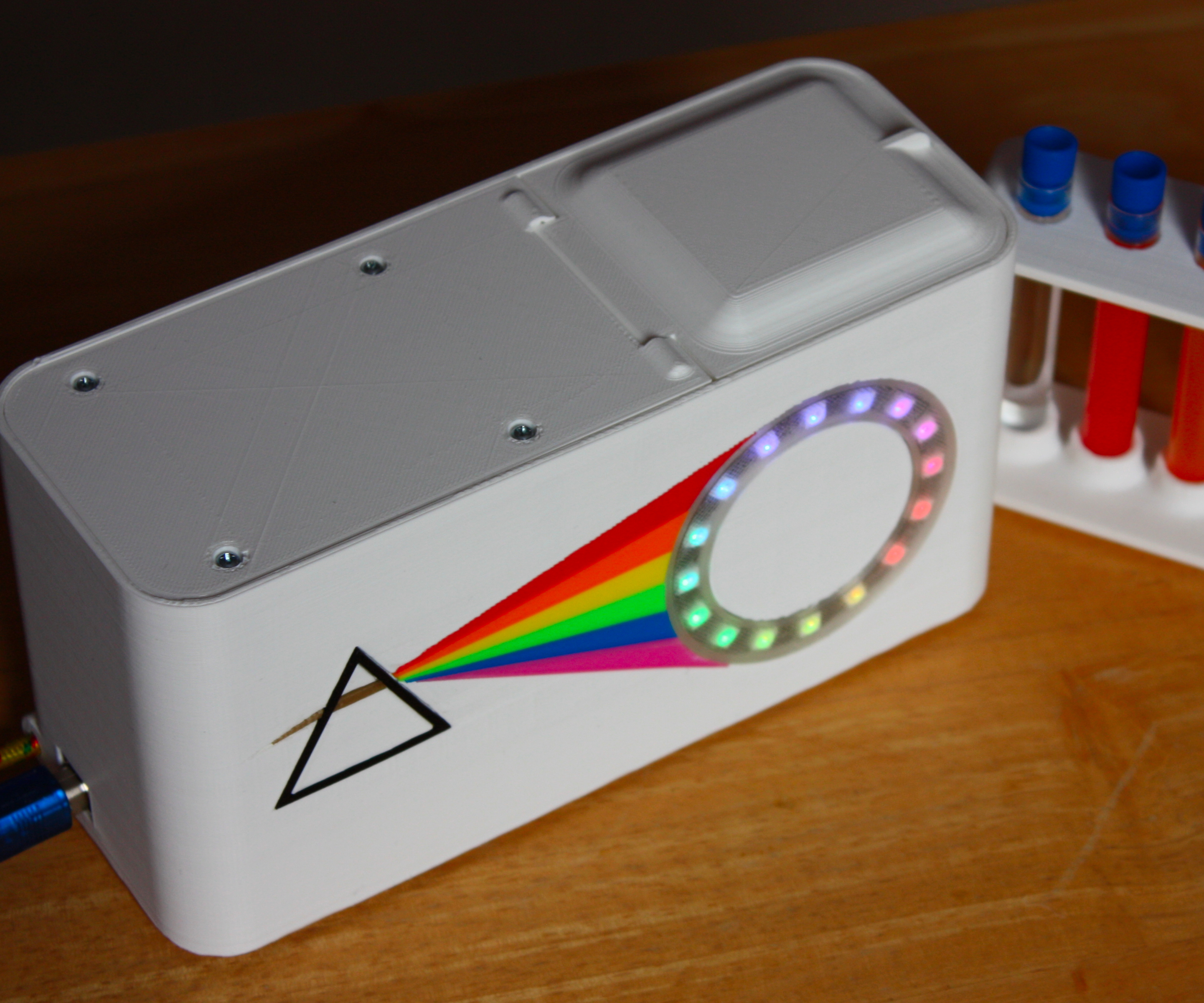
About: Where’s the tea? (previously named ‘dentdentarthurdent’) More About Daniel Hingston »
Update 13/02/21: Since the initial release I have updated the LiDAR code to improve the performance! Please see Step 8 of this Instructable for a video and the updated files. The video also shows a lot more test examples, and tries to explain more detail of how the LiDAR performs. Thank you very much for your feedback and comments so far, it has been interesting to read them ~
In this Instructable we’re going to build a budget spinning LiDAR sensor, powered by Arduino. It cost less than £30 to build ($40) and has a diameter of only 30mm (1.18″). It uses two sensors, diametrically opposed to each other, to double the scanning rate, and is suitable for mounting on top of a small robot. All parts are 3D printed and are suitable for small 3D printers too.
Please have a watch of the video summary to see a step-by-step of the build, as well as footage of the testing! The Instructables guide should then give you all the details you need to reproduce the project yourself.
Safety: There are some sources of risk, from the use of hot 3D printers and soldering irons, but otherwise low voltages are used throughout, and the VL53L0X sensors do not produce a laser which is harmful to the eye. Parental supervision is encouraged if appropriate, but please be exercise care and use eye protection when needed.
Step 1: What You Will Need
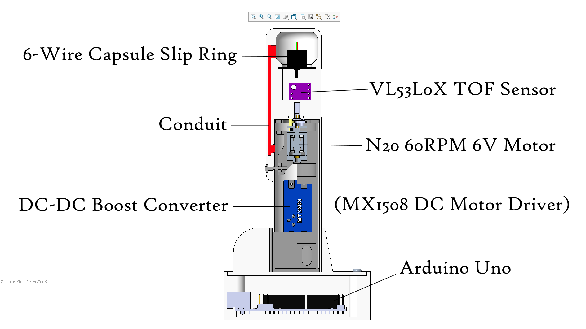
LiDAR ‘Lighthouse’
- 2x VL53L0X TOF Distance Sensors
- MT3608 DC-DC Boost Converter
- MX1508 DC Motor Driver
- 8-Way Molex PCB Connector (Female)
- N20 6V Motor (Micro Metal Gearmotor) – 60 RPM по мотору и датчикам есть еще варианты
- 6-Wire Capsule Slip Ring вращающееся кольцо 6-контактов
- M2.5×12 Screw + M2.5 Nut
Test Base Station ‘Lighthouse Keeper’
- Arduino Uno
- USB Cable
- 5V 1A Wall Plug
- 8-Way Molex PCB Connector (Male)
- 7x Header Pins
- 4x M3x12 Screws + 4x M3 Nuts
Consumables
- Lead-free Solder
- Heatshrink (not necessary but desirable – can use electrical tape instead)
- Electrical Insulative Tape
- Glue (CA superglue would be suitable)
- PLA Filament for the 3D Printer припой термоусадка изолента пластик для 3d принтера
Software
- A PC, running;
- Arduino IDE
- Processing – a graphical library, we’ll use it to show the sensor output on the PC
- CAD software, e.g. Autodesk Inventor – if you wish to modify the 3D printed parts
- Slicing Software – as you use to set up files for your 3D printer
Tools
- 3D Printer такой же инструмент сейчас как дрель например – его за неделю привезут на почту или сразу домой. 9700р.
- Screwdriver
- Soldering Iron, Wire Strippers, Side Cutters
- Craft Knife, File отвертка технический ножик кусачки зачистка для проводов. у нас все есть в Москве на Митино ну или в строительном магазине. Паяльник лучше хороший, а меня паяльная станция с установкой температуры и несколькими насадками, работает уже лет 5!
Step 2: Design
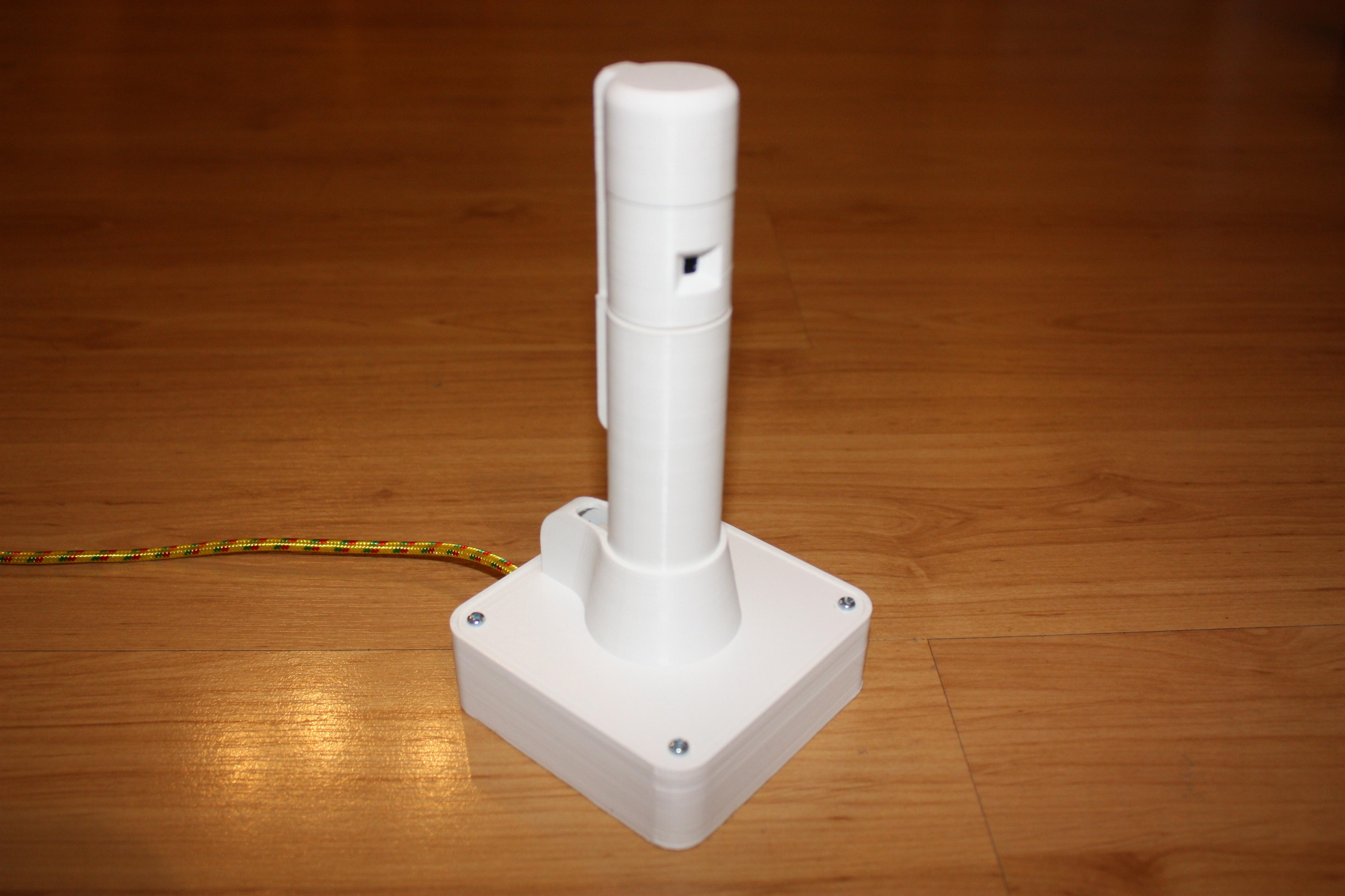
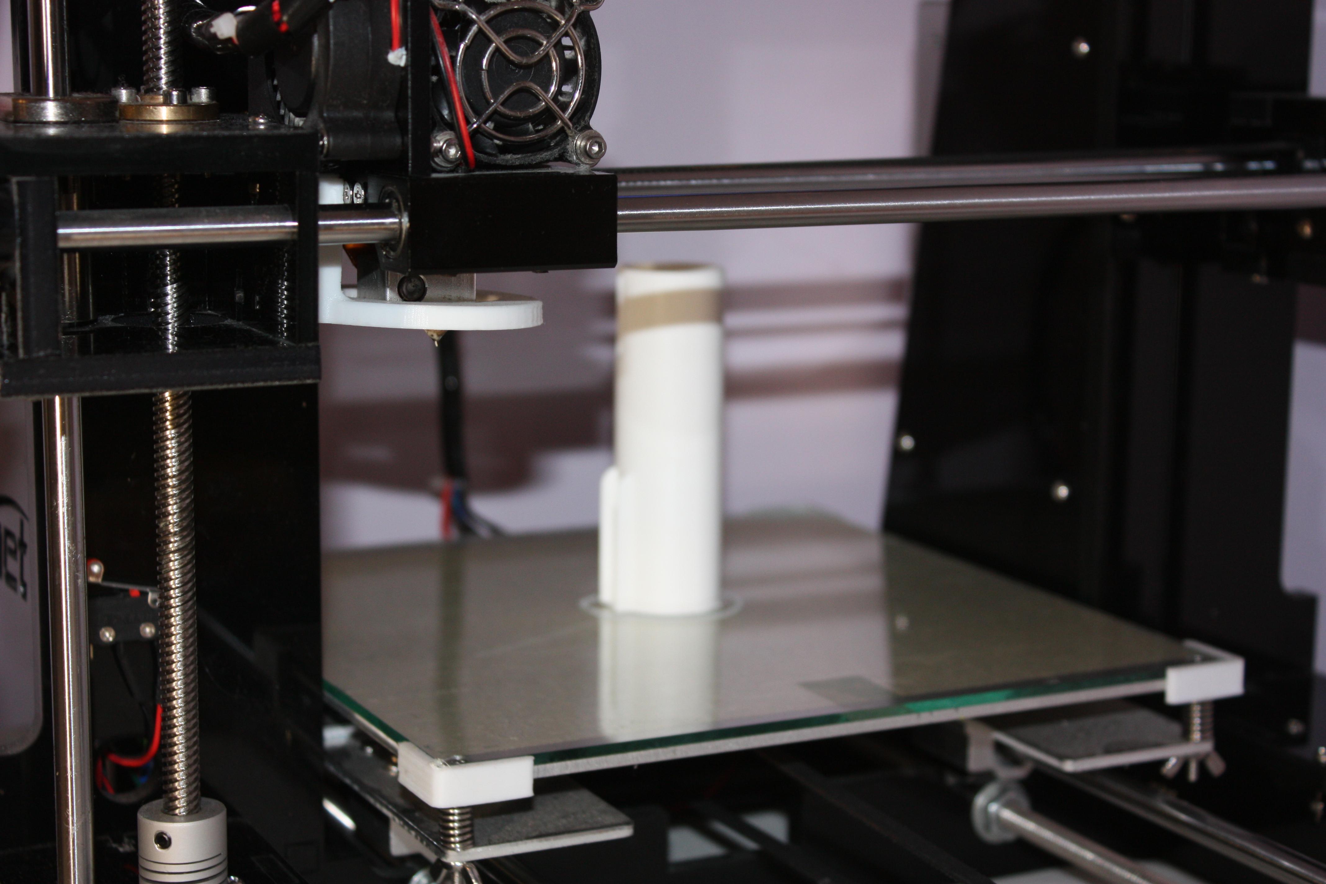
Plastics (and 3D printing) are what makes this project possible! The plastic we use is PLA (polyactic acide, a starch-derived plastic commonly used for 3D printing filament). FDM (fused deposition modelling, the fancy way to describe the filament type printing used in most amateur 3D printers) is an amazingly low-cost way to be able to create high quality and low cost components, without which we couldn’t do this! Making these components another way would be undeniably slower, trickier, and more expensive. The 3D printer I use is an Anet A6, a low cost machine, but more than capable of projects like this one.
если неохота увлекаться трехмерной печатью можно взять бутылку от йогурта или даже трубку серую от слива раковины, а коробку пластиковую от электрики. а вот пистолет с термоклеем ну точно пригодится, 2700р фирменный какой то.
The Design
The key drivers in my design were:
- Low cost – the total price of the components should be as low as possible.
- Minimal size – a focus on maintaining the smallest dimensions possible.
- Performance – a near 360° coverage and fast scanning rate.
Basic and widely-available components are used throughout, and cost is minised by the omission of any form of encoder. This would be use to measure the rotational angle of the scanning head. Instead, a pillar is within the scanning arc of the sensors; from this the rotational angle of the head can be calculated by recording when the sensor detects the presence of the pillar, and then calculating the rotational speed and hence angular interval between distance measurements.
A ‘slip ring’ is a component that allows an electrical connection to be made through a spinning interface, and we use a 6-wire capsule slip ring to take the connections from the two sensors down into the body of the LiDAR tower. By relocating the slip ring to above the spinning head, and then using the pillar to route the wires down into the tower, a very simple layout is created, which utilises a small number of components.
Why a LiDAR?
I’ve wanted to make a spinning distance sensor for a few years since I worked on some basic wheeled robots. I didn’t have the ability to design one then, but I’ve toyed with the design more and more in the last few months, and decided to at last make it happen! Лидар это вариант для игрушки – робота, устройство измеряющее расстояние и можно сделать карту или схему помещения.
Previously I’ve used basic fixed ultrasonic (HC-SR04) and IR (Sharp series) sensors for distance sensing, but never a spinning sensor before. The commercially available spinning LiDAR sensors are quite expensive for me, so I wanted to try and develop a basic one for a very minimal cost. If successful, I planned to use this sensor for navigation of small robots, as well as room mapping.The VL53L0X sensors I chose to use have a wavelength of 940nm, invisible to the human eye but a smartphone camera will show a bright flash! Ультразвуковой датчик сейчас тоже очень точный, особенно есть с микросхемой Сони и с выделением пачки импульсов около 40 килогерц, он на чердаке на даче замерил на 7 метрах расхождение угла 3 сантиметра, точность почти как у лазера, а датчик hc-sr04 несколько дешевле. Второй образец буду делать на 500 выборок в секунду и с датчиком 22 метра (этот на 2 метра) но за 7000р а этот за 1000 и мощности надо меньше.
There are some very good YouTube videos on similar projects that I found inspiring, in particular this video by Electronoobs.
3D View!
It may take a moment to load, but I included this Tinkercad 3D view so you can look at the model yourself:
Step 3: 3D Files and 3D Printing
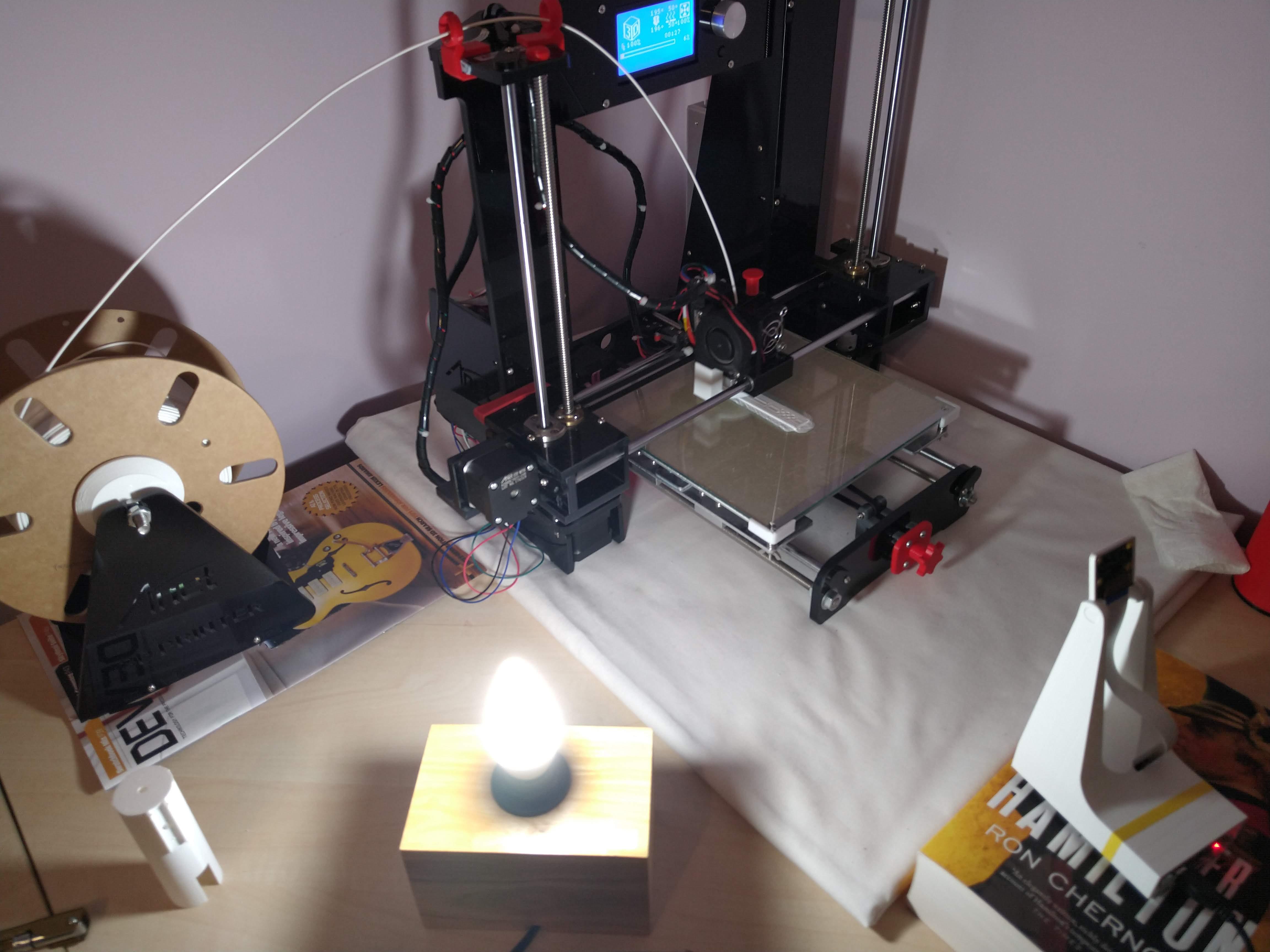
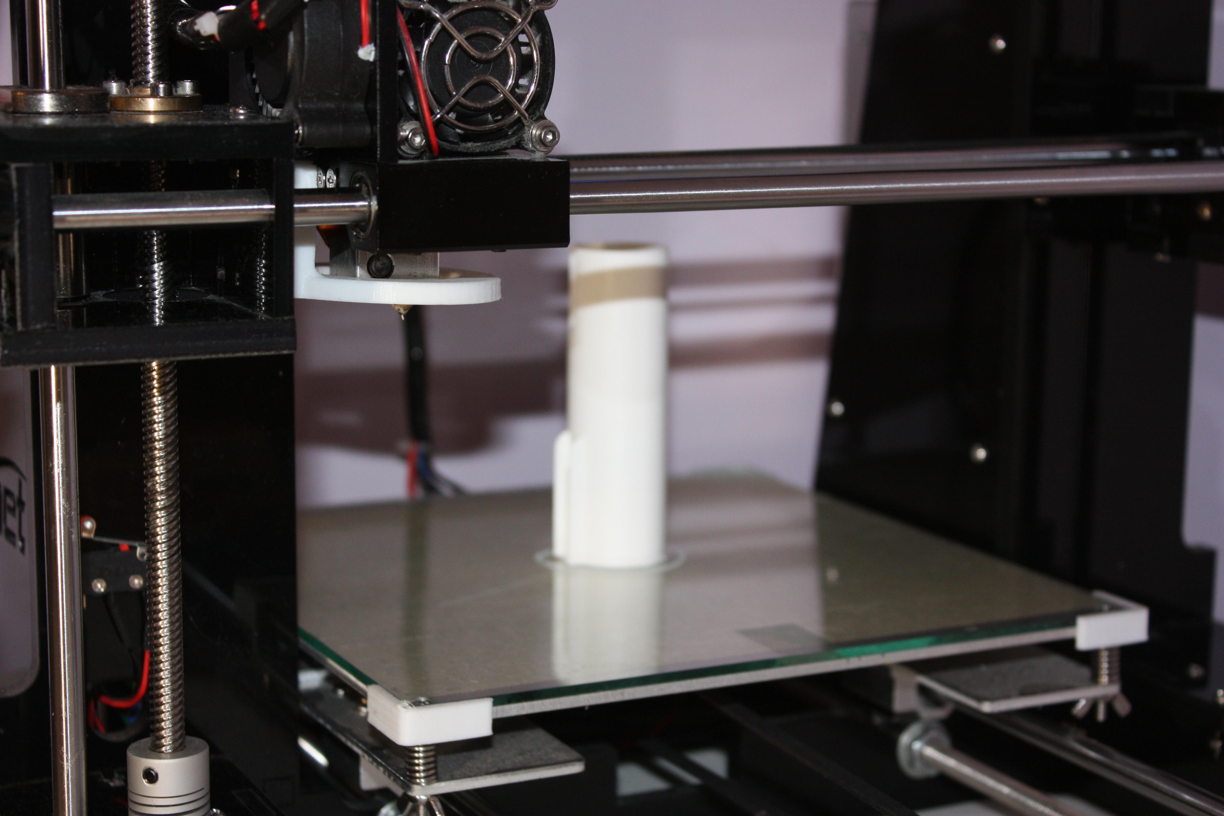
The Files
You can download all of the CAD files from the Grabcad Library I’ve created here. This contains .stl files, ready for you to export to your slicing software and be printed! There are also the project files in .step format. These will be what you need if you want to use your own CAD software to modify the design in any way, or just to adjust the fits and tolerances to suit your components or printing quality.
If you’d like to modify the design, you’ll need to use some CAD software. If you’re not familiar with that, it’s a really useful skill to learn as a maker that will no doubt be useful for lots of future projects! I use both the free version of Autodesk Inventor, which is really easy to learn as a beginner and is very user friendly, and also the educational version of Creo Parametric which is another similar program – there are others too.
3D Printing
There are only 4 printed parts in the Lighthouse tower, which should be printed in the orientations shown. Quality should be maximised as far as possible, I used 0.1mm layer height and a very slow print speed.
Clean up the parts using the side cutters, file, craft knife and test fit the key components to make sure that everything fits comfortably. You’ll find that most components are a little loose, this is deliberate – I use thin pieces of masking or electrical tape to create a nice push fit – it’s easier to make fits tighter than to make them looser!
In the first photo you can see the RPi V2 camera I used to record the timelapses of the printing for the video, as well as the lamp that helped illuminate the prints for the photos. скачиваем файлы они есть готовые и печатаем выбраным пластиком, надо ставить настройку по-медленнее и лучше качество.
Step 4: Electrical Schematic and Soldering
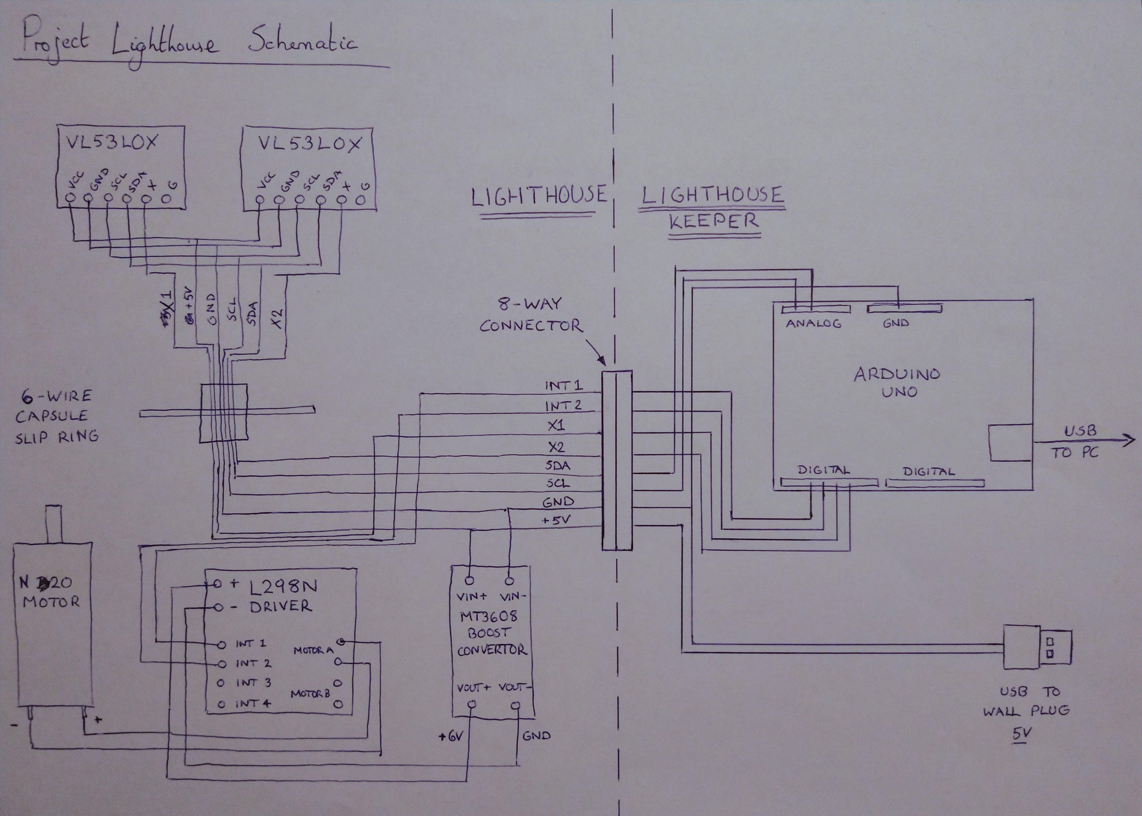
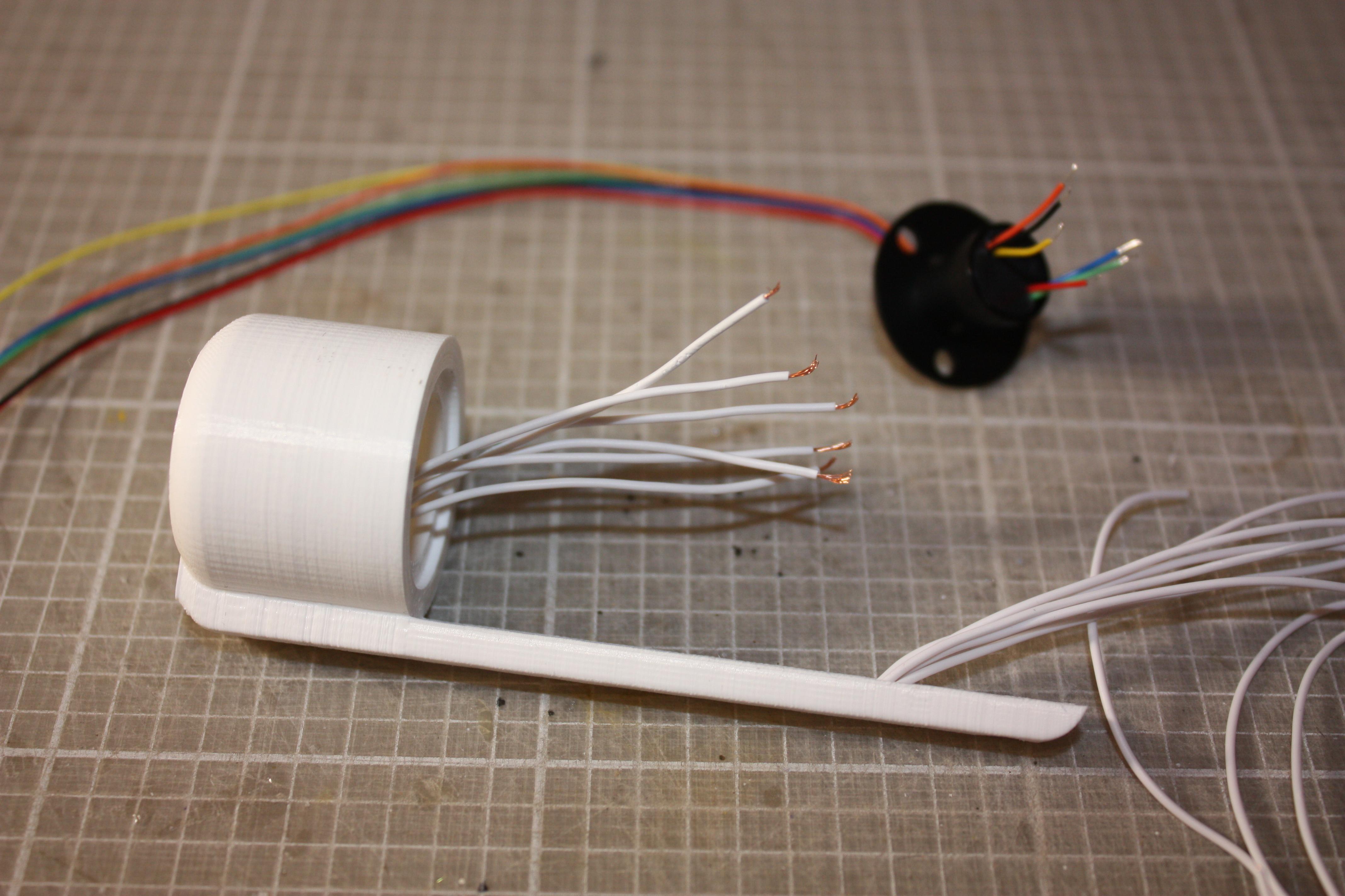
Schematic
Please have a look at the attached schematic to see how this side of the project is done. It’s relatively straightforward – it is split into the ‘lighthouse’ and ‘lighthouse keeper’, in other words the tower and the base station. An 8-way connector provides an interface for power and data between the two. лучше сделать разъем для удобства сборки и настройки
Sensor wires through the conduit
The ‘cap’ part contains a narrow channel down the long stem, which is designed to fit six thin wires as shown. These were a real challenge to fit – I modified the 3D file that’s attached to this Instructable to widen the hole that the cables come out from to make it easier for you (I had to widen mine with a Dremel!). I found it easiest to push the bunch of six together down the channel, and then use a bent paperclip with a hooked end to fish them out of the inside of the cap. This is certainly the hardest part of the build so at least you get it over and done with first… Технология супер папье маше – трубочку согнуть из бумаги и пропустить в дырочки с 6 проводами – я возьму провод мгтф его еще продают, и можно закрепить термоклеем или обычным типа момент.
Slip Ring
Now trim the wires of the slip ring as shown, and solder onto the exposed wires from the cap. Take a multimeter and identify which coloured wire matches which wire ending, I then attached a little piece of masking tape noting which colour cable each wire related to. This will be handy when you come to making the other connections later. на провод трубочку разных цветов и можно подписать что это и откуда. Это не долго.
Lastly get the slip ring glued into the cap, and hold it in place until the glue is set. The lower half of the slip ring with its cables should rotate round easily. 6-контактное кольцо проверить что легко вращается и не задевает.
Step 5: Tower Assembly
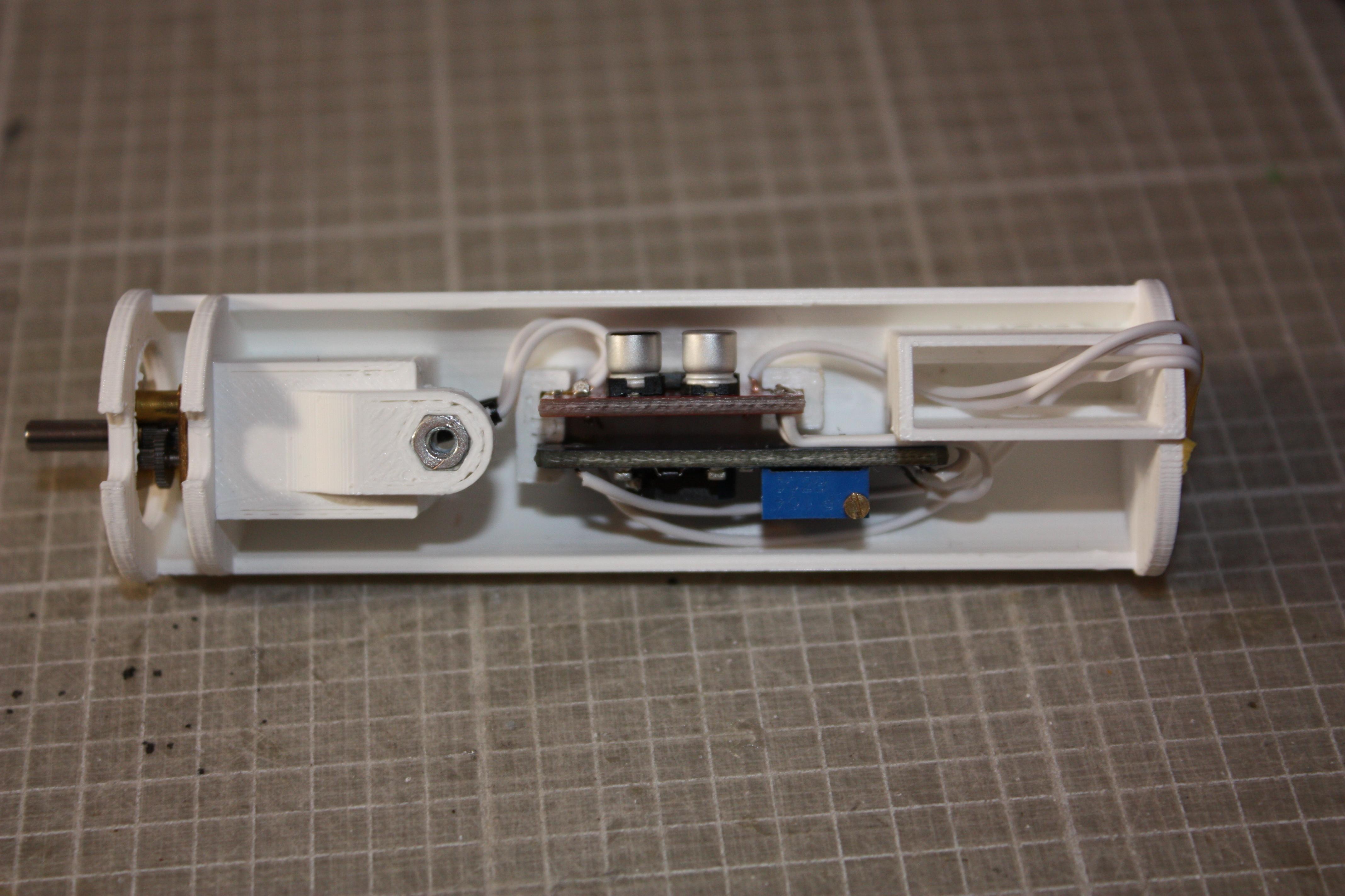
Motor
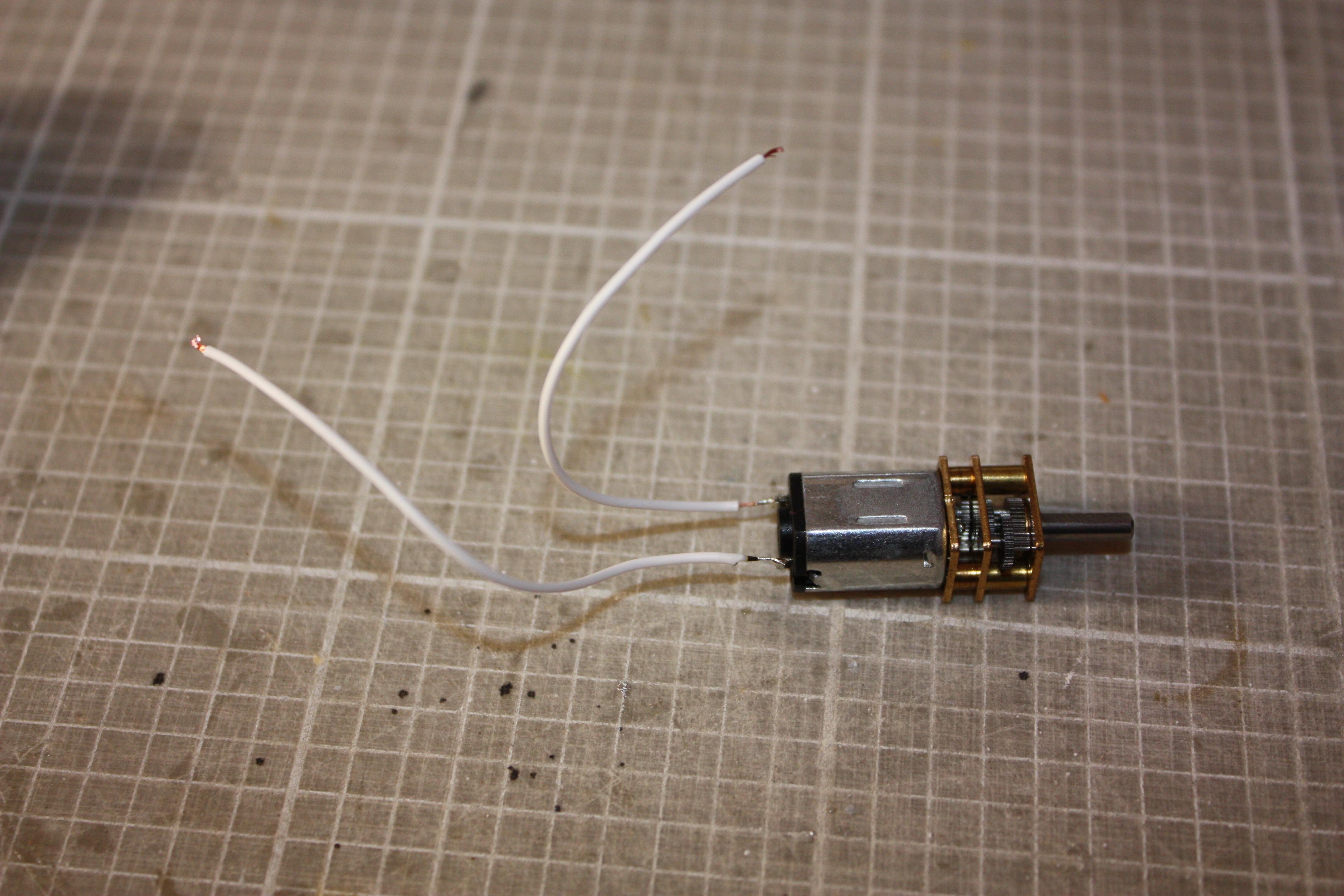
Solder on a pair of short wires as shown onto the motor contacts, and fit it into the motor holder within the ‘carriage’ printed part. I needed to wrap the outside of the motor casing in a few turns of masking tape to take up some spare room and ensure it was a tight and wiggle-less fit. 16 оборотов в минуту он с редуктором.
Motor Driver Board
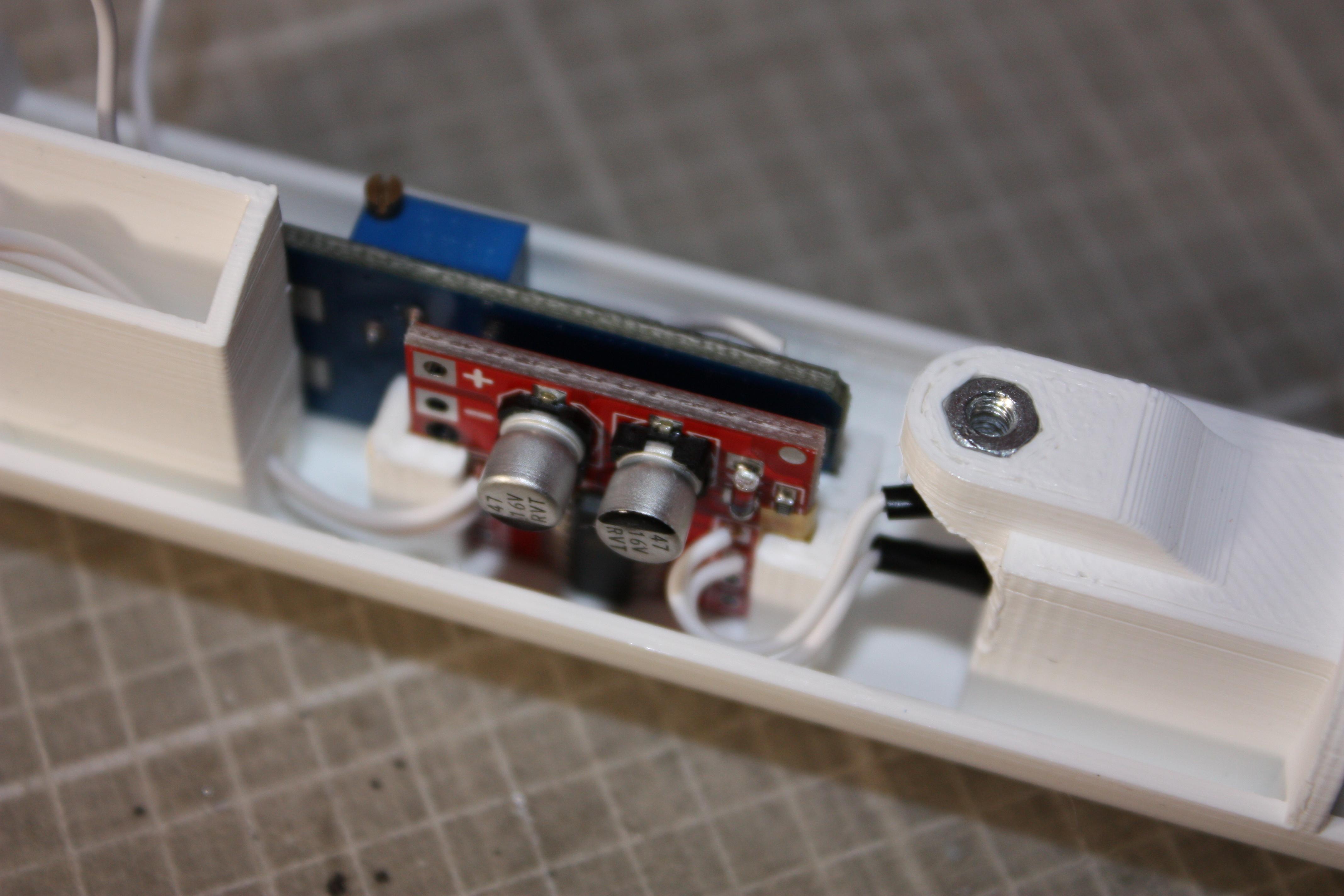
Slot the MX1508 driver board into place and check the fit. You may need to add a little masking/electrical tape up the sides of the board to hold it tightly in the slot that is designed for it. Remove it from the carriage again, and cut the motor wires to length and solder in place onto the ‘Motor A’ contacts. You can now also solder on two lengths of wire (not less than 10cm/3″) to the IN1 and IN2 contacts, that will be used to control the motor driver. Slot the board into its place as shown in the photo. Плата управления к мотору.
Boost Converter Board
Next up is the MT3608 DC-DC Boost Converter! Before installing in the carriage, attach (solder) the VIN+ and VIN- contacts to the wires of a USB cable to a 5V USB wall supply, and adjust the output voltage (by the little screw) to make 6V. Unsolder those leads again, and return the bare board to the carriage. Again check the fit of this into the slot that is designed for it, and add tape to take up spare room if necessary. Now attach lengths of wire to the VIN+ and VIN- contacts, and from the VOUT+ and VOUT- contacts make a connection to the + and – contacts of the motor driver board. As shown in the pictures, you should be able to do this with a neat little length of wire for each. с 5 вольт на 6 плата повышайки – по схеме нужна и может от юсб работать.
Molex PCB Connector
To make it easier to route, use some pieces of tape to gather up the cables that come from the cap. The Molex PCB connector you bought should have lots of little pins like those shown in the pictures, and you’ll need to solder our wires to those for each of the six data lines, plus the +5V and GND lines. Make sure you leave enough length that the cables reach more than a few cm (+ 1″) from the edge of the connector aperture where the Molex connector will sit – otherwise they will be too short and too difficult to work with. Too long though and you won’t be able to fit the spare cable inside the casing when you try and close it later!
Note that you’ll need to have two wires going to the +5V pin (one from the cap bundle of wires, and one from the boost converter) and two to the GND pin also. Little pieces of masking tape again can help you remember which pin relates to what wire to make sure you fit the pins into the Molex connector housing in the right order. You should feel a small ‘click’ when you push each soldered pin into the housing, and this will retain it securely. Finally push the connector housing back into the carriage, to sit flush with the edge. 6 – контактный разьем.
Step 6: Sensor Head & Tower Assembly
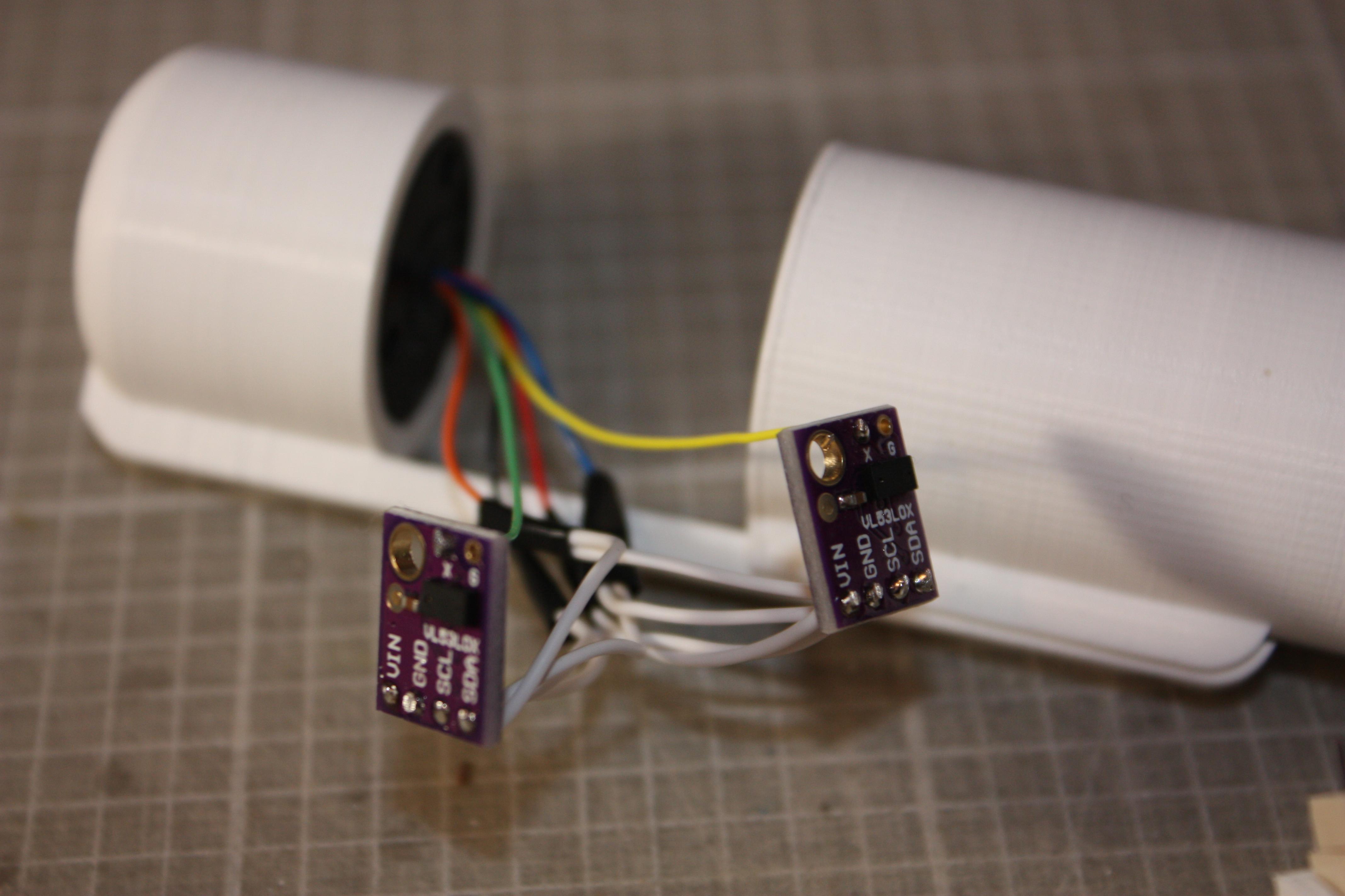
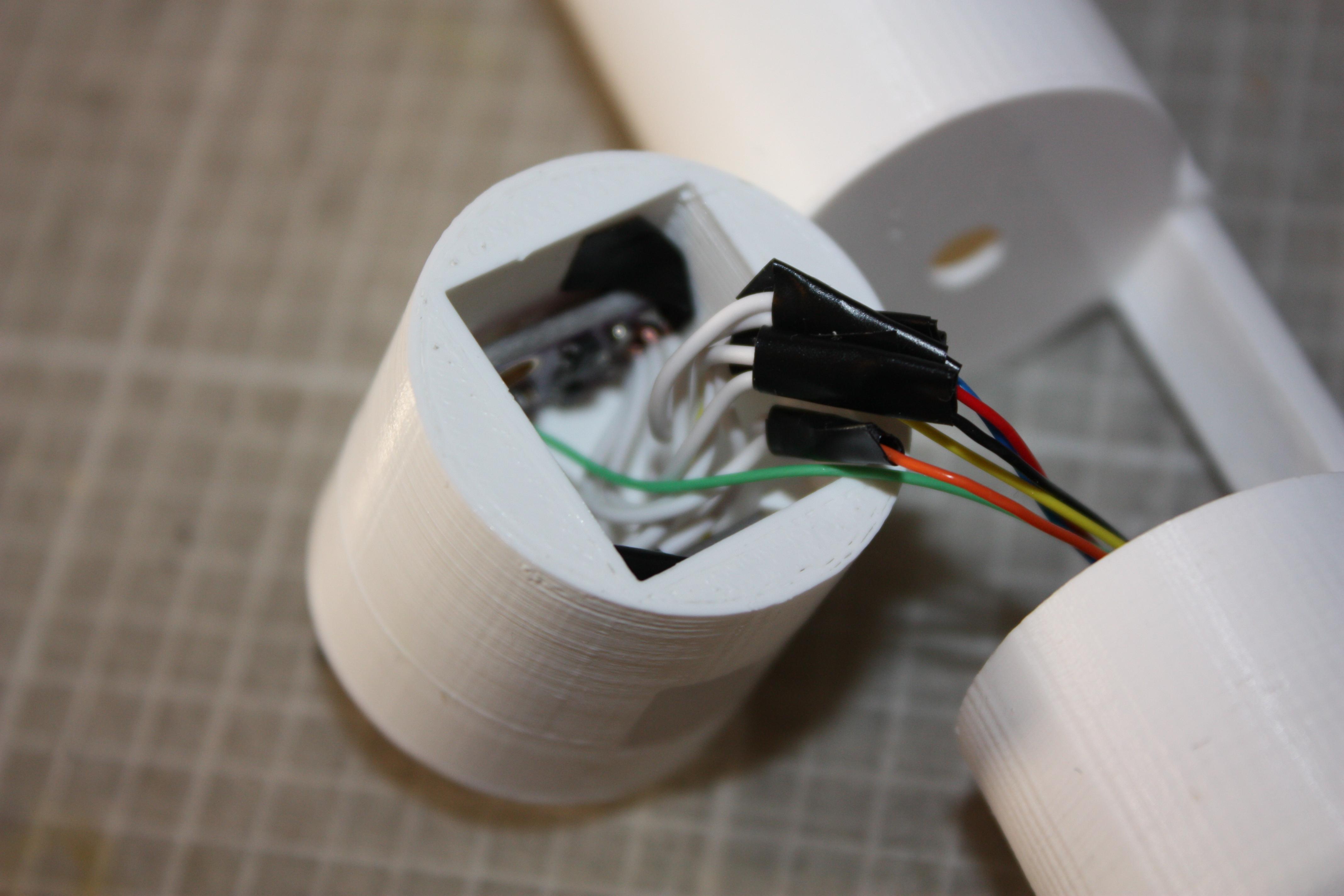
VL53L0X Wiring
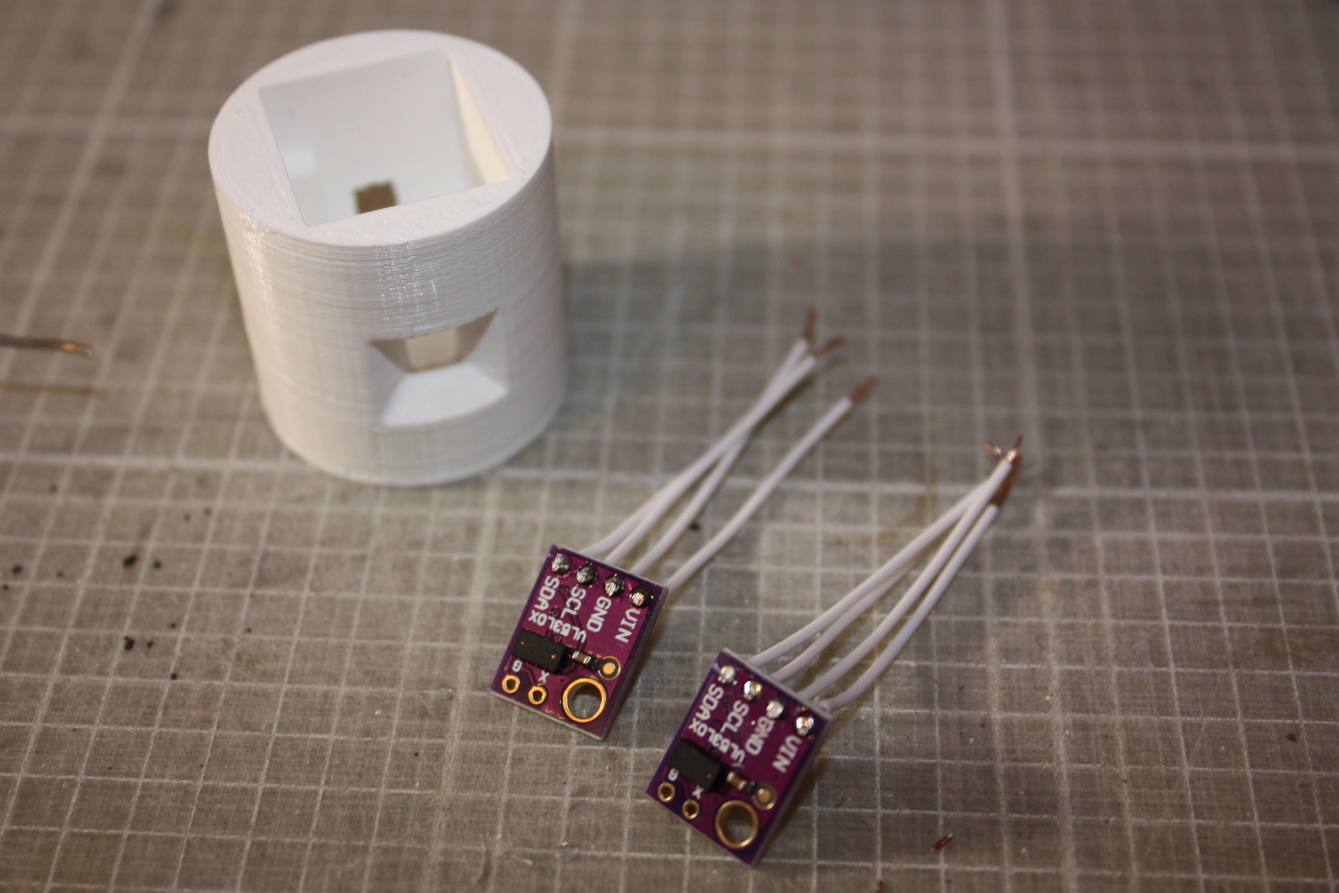
Solder short lengths of wire as pictured to each VL53L0X board, with the leads on the opposite side than the sensor itself. You want to connect the wires to VIN, GND, SDL, SCA, and X (that wire not pictured).
Each VL53L0X has 5 wires connected, so 10 total – however the slip ring interface that these must pass through only has 6 wires! How does this work?
The answer is that the VL53L0Xs share VIN (5V), GND, SDA, and SCL. Twin these wires together between the two boards, and then solder each one of these to one of the slip ring wires (cut appropriately short as shown). The ‘X’ wire from each VL53L0X must each be connected to a unique slip ring wire.
Assembling the Sensor Head
Test the fits of the VL53L0Xs into their holders inside the printed head part. This should be tight to hold them in place. If not, add a little electrical tape along the edge of the board to increase the tightness of the fit. Push both VL53L0Xs into place, and then gently pack the protruding wires down into the void between the two boards.
Tower Assembly
Now you’re ready to assembly the tower! It’s a little fiddly as the tower is so compact, (an extra arm is recommended if you have one) but if you watch the video (in the first step of this Instructable), you’ll see the technique needed. The process is also shown by the final four images above – it’s a case of sliding the carriage into the tower, whilst aligning the sensor housing and cap. Don’t screw the M2.5 screw in the tower in too forcefully, as you’ll distort the carriage piece within the tower’s walls, and this will place strain on the motor shaft and cause misalignment.
Step 7: Base Station – the ‘Lighthouse Keeper’
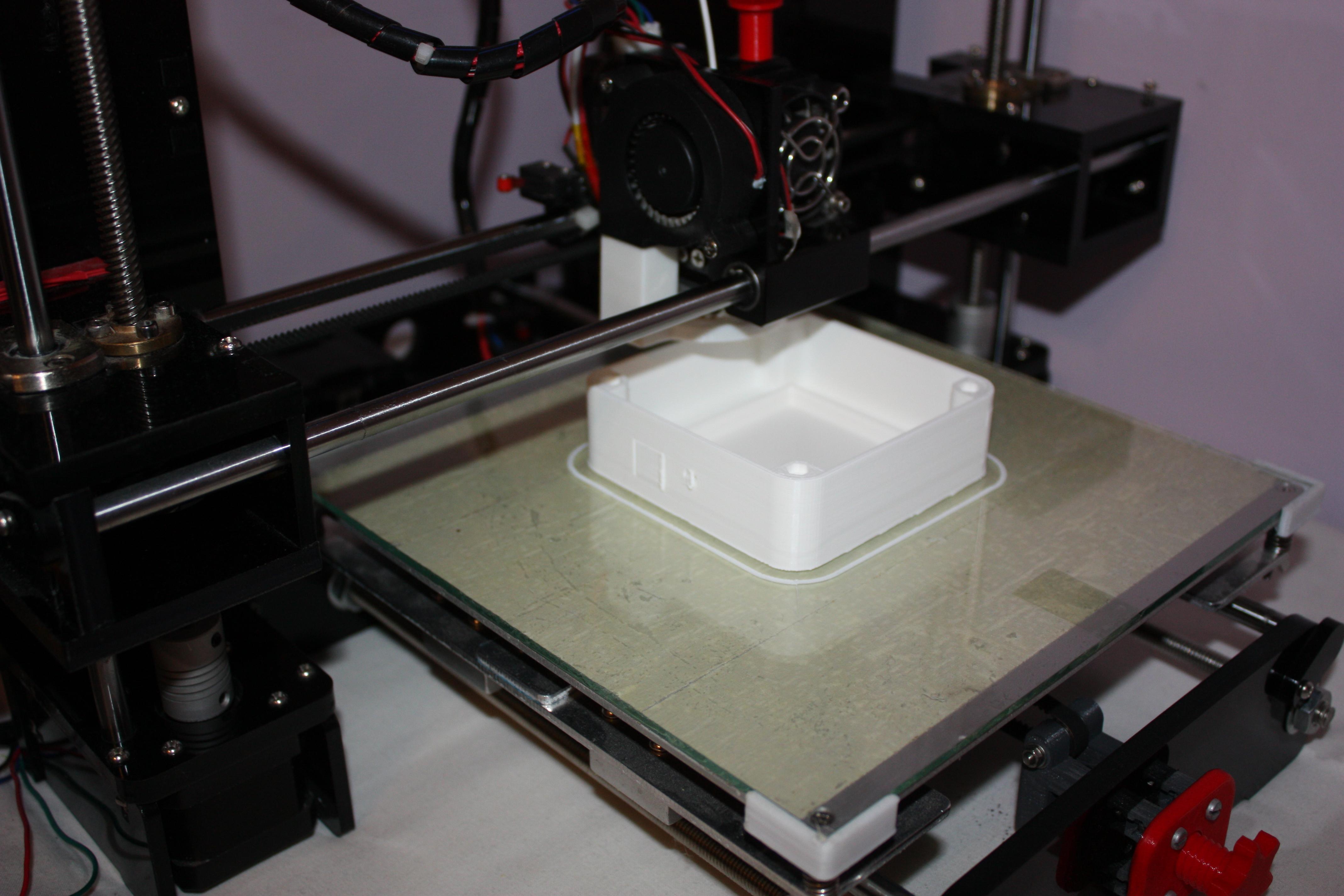
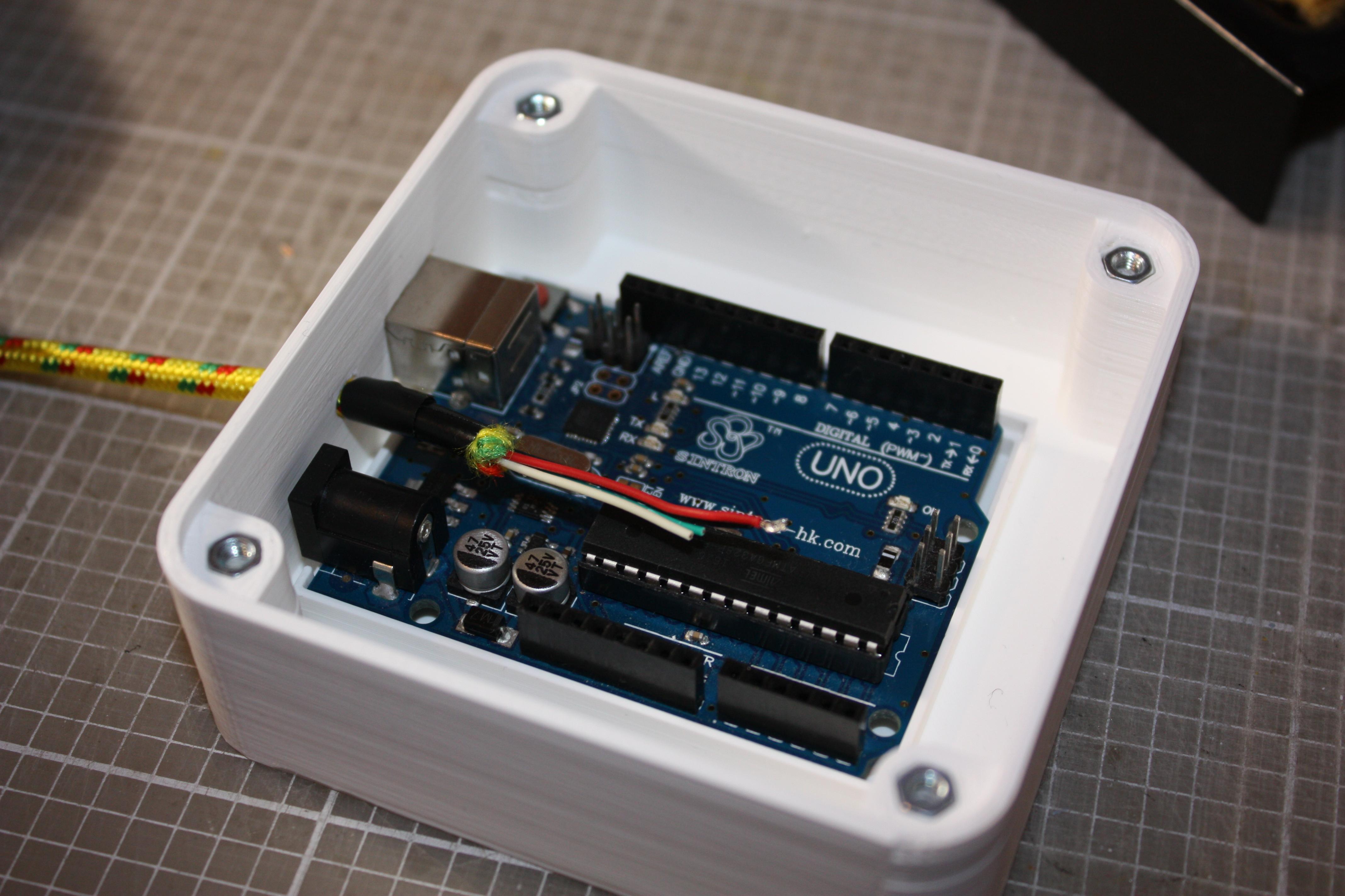
The LiDAR is designed to be mounted onto any kind of small robot, but for testing I designed this small base station. It houses an Arduino Uno, and the interface to a 5V wall supply, as well as an 8-way male Molex connector to interface to the ‘Lighthouse’. It represents the power supply and control interface of a generic robot, and for testing allowed me to develop the LiDAR’s code and test the function.
It is printed in two parts, a base, and a lid, which are joined with 4x M3x12 bolts and nuts. The Arduino is friction-fitted into the base. I use a 1m-long USB cable to provide power from a 5V 1A wall plug. Cut this wire open, and select the red 5V and black Ground lines as shown. The Arduino will draw its power over the USB to PC connection, but it is important to join the GND pin of the Arduino to the input Ground line from the wall plug.
Solder up the other lines to the Molex connector, and shroud in insulation tape like shown. Make sure you have double-checked for shorting, and make sure your pins on the base station connector match the pins on the lighthouse tower!
The connector plugs into the female connection of the tower as shown, which then sits snugly on top of the base station. We’re ready for programming now, so please read on.
Step 8: Programming
Update 13/02/21: Since the initial release I’ve spent some more time improving the code. The new, updated files are those attached to this step, so please download and use these. I also made the video, below, to explain what has changed since the first release, and to show you more testing examples!
The full Arduino program is attached to this section of the Instructable. Please download this and make sure you also install the “Adafruit_VL53L0X.h” library.
Also attached is a Processing program. Processing is an open-source graphical library, and we’re going to use this to visually display the LiDAR output on a computer screen. It takes the Arduino data returned to the PC via Serial communication, and presents this as a graphical plot that shows the data being returned.
Both programs are annotated to explain the function of all aspects of them so you can more easily understand and use/modify them yourself. Please ask in the comments if you have any questions!
Upload the Arduino program to the Arduino in the base station. With the Arduino connected to your computer, initiliase the Processing software. ‘Run’ the processing program attached, and it will initialise a black rectangular full-screen window with a small white circle in the centre. The small circle represents the diameter of the sensor itself, while the larger circle represents the maximum range of the sensor as set/limited by the Arduino code.
The motor will begin to run, and will complete approximately 10 rotations. This is a calibration stage in which it measures the rotational speed of the motor, and calculates how many readings it will take per revolution. This information is later used to ascribe a particular angle to each distance measurement taken, in increments.
After the calibration is complete, small dots will begin to appear on the screen, showing where the LiDAR is sensing objects in its vicinity. Read the next step for more testing information! калибровка двух программ – по 10 оборотам сенсора, измерения будут представлены на экране по кругу – после загрузки скетча в Ардуино конечно.
Attachments
Step 9: Static Testing
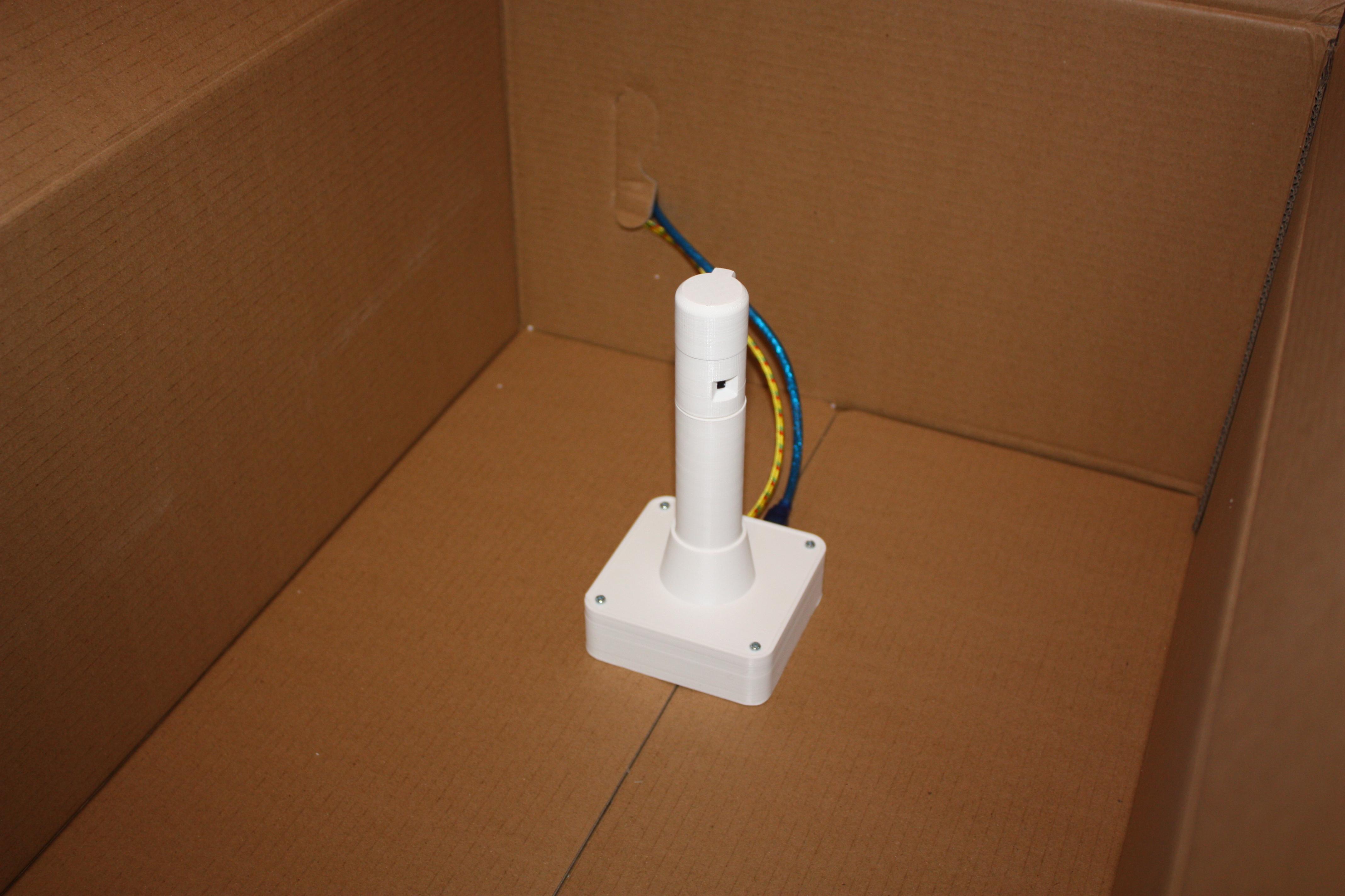
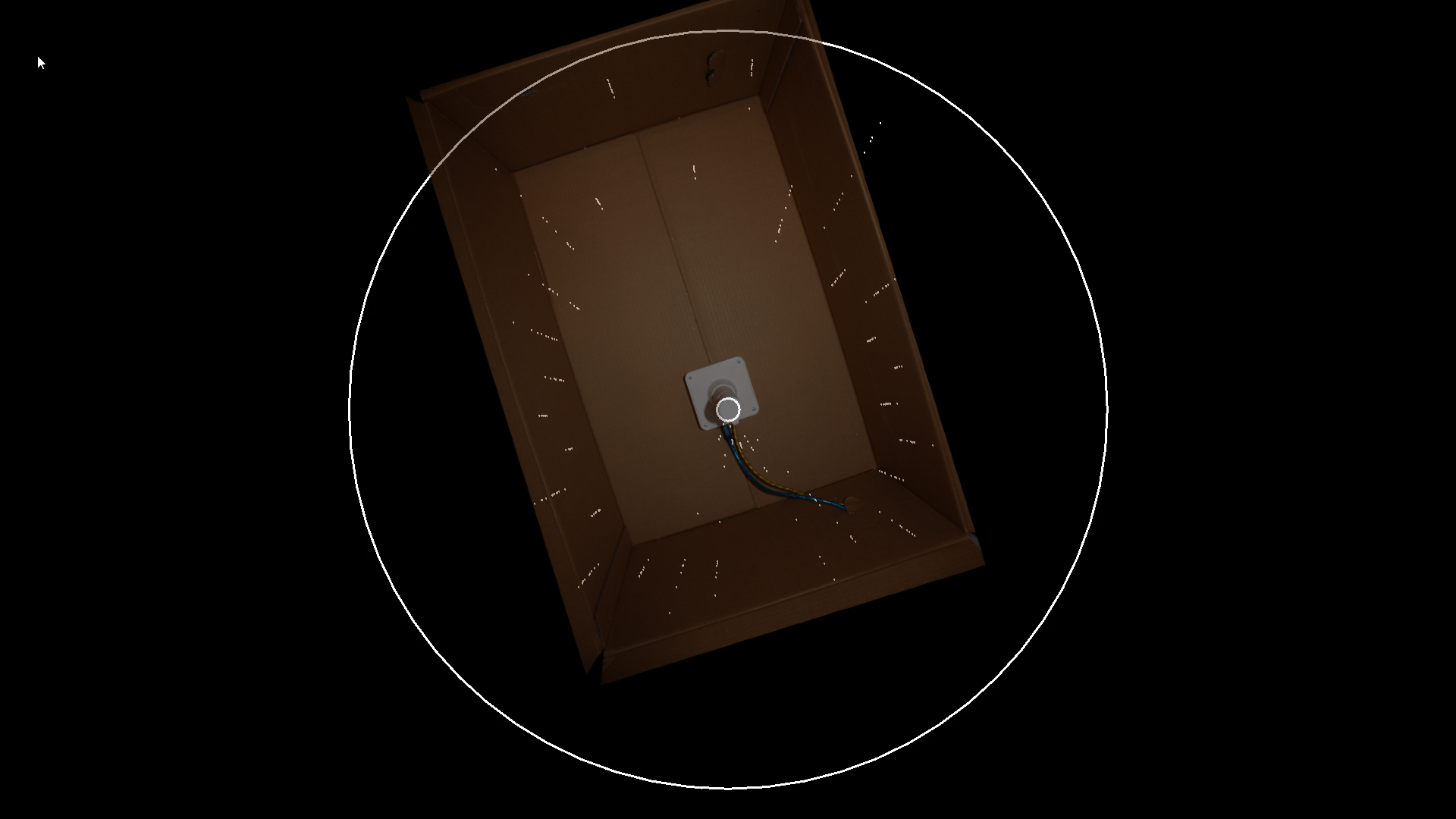
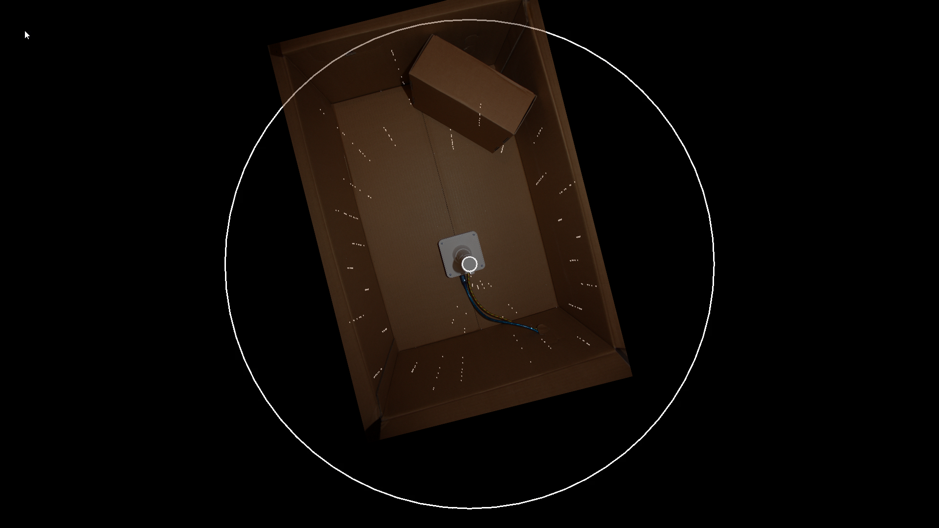
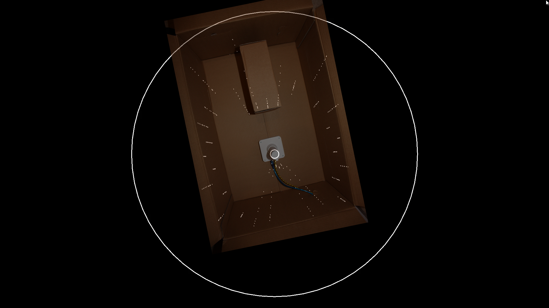
To test the LiDAR’s function, I used a large cardboard box as shown to create a controlled environment for taking the readings. This meant that the expected picture that the LiDAR would see would be very simple, and make the results easy to interpret, compared to looking at a whole room for instance!
By placing small objects like the smaller (filament reel) box shown into the field of view of the sensor, we can see in the test results how it was successfully able to detect the position of the object. I have overlaid images of the box on top of the corresponding test results to see how well the sensor was performing – it was quite pleasing results. You can also see at the bottom of the images where there is a cone-shaped segment (about 40°) which is the portion of the view that is obscured by the LiDAR tower’s pillar.
Compared to a basic fixed sensor for instance, it was exciting to be able to record this level of detail – whilst pretty basic it is still a big step up and I am really keen to try testing it as part of a small wheeled robot next, but that’ll have to be another project …
Step 10: Conclusions

Update 13/02/21:I updated this section following the code update (see Step 8!)
Overall this has been very interesting project to build, and it’s gratifying that the initial results are quite promising. There’s a lot more that could be developed with it, but it’s exciting that it’s already capable of simple mapping of its environment.
There are some things that I’d like to do a bit better if I were to design another sensor:
- Look at ways to reduce the time interval required to read the sensors. In the initial release it took more than 100ms to do a read cycle. Following the code update (see Step 8), I managed to reduce this to 57ms, allowing much more data to be recorded per rotation. I think the VL53L0X is now the main limiting factor, not the code, the Arduino or the rest of the Project Lighthouse hardware, as the sensor is limited to 20ms as a fastest possible read time, and this project uses two of them. The only way I can think of accelerating this further is possibly by having both sensors controlled independently by separate Arduinos (Pro Minis?) that then pass their data to a central controller, this way they could record their data in parallel, rather than each sensor one after the other …
- More complex data-recording. I think a more complete picture of the surroundings could be built up by adding a small time delay between the recordings of each successive rotation – this would have the effect of offsetting each rotation’s data-set by a few degrees. After a number of rotations this could have the effect of building up much denser data than the small number of angles that I currently record data for.
- I am aware that currently the code doesn’t account for the rotation that occurs between the reading of the 1st and 2nd ToF sensors – this was a deliberate simplification, but would be an interesting aspect to try and account for in the code.
So thank you very much for reading, and if you’re interested in making one yourself I hope it gives you a fun and rewarding project. 
Second Prize in the
Plastic Contest
Be the First to Share
Did you make this project? Share it with us!
лидар это лазерный радар – обычный сканер. Но знакомый его чуть переделал – и в комнате ни одного комара, только в добавок – слегка прожженые обои..
опасность от лазерного импульса преувеличена, но осторожность не помешает. углекислотный 7 ? ватт картонку прожигает.
** Пулемета я вам не дам, да и время сейчас.. вся комната это лазер. не, на столике кювета из огрстекла, там какая то красная только зеленка. Трубочки из кварца с ксеноном. Бабушка делала с помошницами, она тот еще химик, вообще из лесного народа чудь, литейщица вроде в четвертом поколении. Расплавлю хоть карбид вольфрама, таким синим огнем можно сделать все. Плазма с электро дугой. Канай! за стену из свинцовых кирпичей, укрытие. Даже как то не интересно, щелк и все. Шестнадцать банок по 50 киловольт, кондеры, заряжать надо опять , у большого прибора с фарфоровым конусом – стрелка на нуле. Иди смотри, вот в мишени дырочка.. пластинки мишени вообще нет, брызги из вольфрама, шарики и налет белый – как от сгоревшей спирали лампы.. (это на лидар как раз) Не секретно уже, но скоро такую штуку можно будет в руках унесть, не, все таки гш-23 надежнее.
