набор конструктор недорого . активные проекты – часы на ГРИ – усилитель на радиолампах с зеленым глазком и 2 индикаторами ИН13 – фонарь 900 люмен на светодиодной лампе, 3 часа на 2 батарейках 18650 – радар на ардуино используя ультразвук – светодиодная линейка для цифровой техники как в старых ЭВМ – в основном с применением dc-dc на mc34063 в нескольких вариантах, 12 на 5 вольт и 3 на 207 вольт , 12 на 200 и 600 преобразователь напряжения.
для часов применяется Arduino nixieclock.biz Arduinix / варианты программы под включение индикаторов постоянным током – в статике, также используются все эффекты быстрого переключения. * arduino = Atmega328p и вариант на 16 мегагерц кварцем – преимущественно за 5 (3 )доллара не за 55.
Я разработал Arduino-совместимый модуль драйвера трубок Nixie, чтобы сделать такие проекты намного проще!

+483 Запостил dekuNukem 01.03.2018 17:40
что то стал програмки Ардуино скетчи редактировать в Akelpad с несколькими дополнительными програмками – показывающими коды -они же делают простую проверку правильности синтаксис. файл записываю с расширением c bas asm . плагины позволяют выбрать подходящий язык программирования.
часы на индикаторных лампах. Комплектуха 6 штук для статики К155ИД1 (можно упростить поставив одну или две – только будет динамическая индикация), кристалл Atmega328p на 16 мегагерц – Arduino CH340g (Chinese). Лампы ИН12 ИН1 ИН16 – самые маленькие а то и ИН18. в случае статики 3 регистра 74HC595 а если плата с динамической индикацией – pc817 6 штук или tlp627 и -или – 6 пар транзисторов mpsa92 mpsa42 (кт503е кт3102г подобрать по параметрам надо 180 вольт) . В преобразователе напряжения mc34063 а второй вариант использовать от ардуино pwm. Катушка – смотрим запись Фонарик на светодиоде или Часы nixie – от блока питания компьютера желтое кольцо (заказать в Китае Индуктор 15А и домотать вторичную, еще лучше если есть альсифер еще из СССР колечки).
- +37 dekuNukem 01.03.2018 17:41 Я полагаю, что многие люди были соблазнены ярким оранжевым свечением трубок Никси, однако эти трубки требуют высокого напряжения питания, старых микросхем драйверов и схем мультиплексирования. И я полагаю, что эта сложность отпугнула многих энтузиастов с проектами. Я тоже думал о создании собственных часов Nixie, и вместо традиционного подхода я решил разработать специальную плату драйверов, называемую exixe. Модули exixe работают с трубками Nixie IN-12 и IN-14 и устраняют необходимость в старинных чипах и мультиплексировании. Вы просто используете 3-х проводный SPI для управления яркостью каждой цифры плюс подсветка RGB. Эти модули просты в использовании, интегрируемы и могут использоваться повторно. Вы можете использовать Arduino, Raspberry Pi, STM32 или что-нибудь еще с GPIO. И, конечно, этот проект с открытым исходным кодом, поэтому, пожалуйста, прочитайте подробности здесь: https://github.com/dekuNukem/exixe Я также провел небольшой производственный цикл, поэтому не стесняйтесь получить несколько, если вам интересно: https://www.tindie.com/products/dekuNukem/exixe-miniture-nixie-tube-driver-modules/ Откладывая в сторону, я надеюсь, что этот проект снизит входной барьер в проектах труб Nixie. Никси труба Ретро метроном? Youtube суб счетчик? Непрочитанные сообщения уведомителя? Таймер ускоренного запуска / секундомер? Хипстерский мультиметр? Так много интересных проектных идей! В любом случае, спасибо за чтение и не стесняйтесь задавать вопросы.
- +8 -Argih 02.03.2018 13:09 Отправить один на EEVLOG почтовый пакет, я думаю, это было бы здорово для вашего бизнеса
- +3 Lewtfish 01.03.2018 20:41 Есть ли шанс, что вы можете отправить в Нидерланды? Хотел бы иметь немного!
- +3 dekuNukem 01.03.2018 21:41 Конечно! Стоимость доставки во всем мире одинакова. Подробности см. В разделе «Информация о доставке» на этой странице .
- +1 ShitInMyCunt-2dollar 02.03.2018 08:11 Есть ли шанс, что IN-16 сработает? Или они принципиально разные?
- +3 dekuNukem 02.03.2018 09:13 Я только что взглянул на таблицу данных IN-16 , похоже, она будет работать. Расположение анодного штифта такое же, и трубка может поместиться на модуле. Порядок цифр отличается, поэтому вам нужно будет настроить программное обеспечение, но с аппаратной точки зрения я думаю, что это совместимо.
- +1 ShitInMyCunt-2dollar 02.03.2018 09:20 Благодарю. Я купил их давным-давно, и у меня были бесконечные проблемы с тем, чтобы заставить их работать так, как я этого хочу – главным образом потому, что я недостаточно знаю, как правильно их водить. У меня есть старые советские чипы, которые специально созданы для них, но, по сути, мое программирование недостаточно хорошее. Я безнадежный. Я ждал что-то подобное, чтобы прийти вместе. Надеюсь, я смогу воспользоваться этими вещами.
- +3 dekuNukem 02.03.2018 09:13 Я только что взглянул на таблицу данных IN-16 , похоже, она будет работать. Расположение анодного штифта такое же, и трубка может поместиться на модуле. Порядок цифр отличается, поэтому вам нужно будет настроить программное обеспечение, но с аппаратной точки зрения я думаю, что это совместимо.
- +1 albionhere 02.03.2018 07:33 Я абсолютный n00b, так что это может быть глупым вопросом. Недавно мне дали комплект для изготовления трубок VFD. Может ли это сработать и для тех?
- +1 dekuNukem 02.03.2018 18:29 Трубка VFD требует совершенно другого способа вождения, поэтому она не совместима с модулями exixe.
- +1 DracarysMeansFire 01.03.2018 17:48 Выглядит очень круто, я ищу NOS NIXI, и когда я их нахожу. Вот как я буду их использовать.
- +6 Zouden 01.03.2018 18:36 Вау, действительно хорошая работа! PCB профессионального уровня, даже имеет закругленные углы! Что такое QFP, чип Atmega?
- +7 dekuNukem 01.03.2018 18:43 Это STM32F042K6T6, универсальный маленький чип.
- +4 vivalarevoluciones 01.03.2018 23:13 Боже мой, я просто потратил много времени на изучение этого, купил несколько тюбиков амазонки, которые все испортились, поэтому я закончил получать этот комплект. http://www.arduinix.com/
не могу дождаться, чтобы спаять мой комплект вместе. редактировать Черт, брат, после прочтения комментариев, я должен был дождаться, дам, это намного лучше. я ненавижу торопиться с покупкой запчастей. - +2 bestofpawnee 01.03.2018 18:24 Это действительно круто!
- +1 bpoag 02.03.2018 16:11 Хочу хочу хочу хочу хочу хочу .. Вы должны продать схему Sparkfun ..
- +1 dekuNukem 02.03.2018 16:57 Я думаю, это было бы слишком нишевым для них, чтобы продать, в любом случае у меня есть несколько на Tindie, так что посмотрите, если вы заинтересованы.
- +1 zappadoing 02.03.2018 20:08 так круто! Благодарю. приказал.
- +1 dekuNukem 02.03.2018 22:15 Спасибо за поддержку! Здесь вечер пятницы, и я отправлю их в следующий понедельник. В то же время, пожалуйста, не стесняйтесь взглянуть на руководство по началу работы, чтобы увидеть, что ждет впереди.
- +1 zappadoing 02.03.2018 20:08 так круто! Благодарю. приказал.
- +1 dekuNukem 02.03.2018 16:57 Я думаю, это было бы слишком нишевым для них, чтобы продать, в любом случае у меня есть несколько на Tindie, так что посмотрите, если вы заинтересованы.
- +1 would_you_date_me 02.03.2018 07:45 Трубы Никси шумят, когда они переключаются?
- +3 dekuNukem 02.03.2018 09:15 Нет, они полностью молчат. Они также потребляют небольшое количество энергии (2,5 мА) и совсем не нагреваются.
- +1 maedhros338 02.03.2018 00:38 Хорошая работа! Отличная идея и выглядит как отличное исполнение. Не могу дождаться, чтобы попробовать их сам!
- +1 Terradice 02.03.2018 08:06 Черт, дай мне, мне нужно
- +1 steeeeeeved 01.03.2018 23:47 Эпическая работа, сэр!
- +1 DrTBag 02.03.2018 11:12 Выглядит как хороший проект, и вы выбрали отличную цену. Я надеюсь, что это хорошо для вас.
- +1 MrScafir 02.03.2018 07:46 Это так круто! Спасибо за это и еще больше спасибо за то, что сделали его открытым исходным кодом!
- +1 ancientsceptre 02.03.2018 04:45 Я люблю тебя
- +1 Rxke2 02.03.2018 12:58 Можно ли использовать другие ники, паяя их проводом к платам PCB, или PCB оптимизированы для эксклюзивного использования с 12-14?
- +1 dekuNukem 02.03.2018 16:51 Вы можете использовать другие трубки для этого, но расположение выводов трубки будет другим, поэтому вы должны убедиться, что они подключены правильно. Например, труба IN-16 будет работать с модулями exixie-14.
- +1 lancelon 02.03.2018 15:45 / и / sanels
- +1 sanels 02.03.2018 21:49 да, я видел это. но это просто делает вещи слишком лол (и много дороже)
- +1 FRESH_OUTTA_800AD 04.03.2018 19:58 Какой хороший источник труб? Это все старые акции СССР? Изменить, только что нашел вашу ссылку на этом
- +1 FRESH_OUTTA_800AD 06.03.2018 03:23 Очень круто! У вас есть еще фотографии, которые демонстрируют возможность подсветки? Или это больше о продавце трубки?
- +1 fefemess 06.08.2018 20:32 Я давно искал что-то подобное. Спасибо. Эль Пси Конгруо
- +1 [deleted] 02.03.2018 20:58 Впечатляет. Выглядит профессионально и гладко, как ад
- +1 fischoderaal 02.03.2018 17:38 Приветствия для этого с открытым исходным кодом!
- +1 joe0400 01.03.2018 19:58 Ваша доставка в Великобританию? Можно ли отправить в США? Мне нужен лучший комплект Nixie от Arduino.
- +2 dekuNukem 01.03.2018 21:38 Да, я отправляю в обе эти страны. Смотрите эту страницу для деталей.
- +1 drimago 27.04.2018 15:05 Этот продукт идеально подходит для моего проекта. Один вопрос, однако: как вы приводите их в действие? Мне все еще нужен преобразователь 5В в 180В?
#include <mega8515.h>
#include <delay.h>
#include <bcd.h>
#include <avr_eeprom.c>
#include <mega8515.h>
#include <delay.h>
#include <bcd.h>
#include <avr_eeprom.c>
#include <I2C.c>
#include <disp_out.c>
#define snd PORTB.0 //нога пищалки
#define pen PORTA.4 //нога power enable высоковольтного источника
#define RTC 0b11010000 //I2C-адрес часов
#define sec_addr 0x01 //адреса регистров микросхемы RTC
#define min_addr 0x02
#define hrs_addr 0x03
#define day_addr 0x05
#define mnth_addr 0x06
#define year_addr 0x07
#define a_sec_addr 0x0E
#define a_min_addr 0x0D
#define a_hrs_addr 0x0C
#define a_day_addr 0x0B
#define a_mnth_addr 0x0A
#define a_flag 0x0F
//команды через RS-232
#define start_cond 0x80
#define set_time 0x81
#define set_date 0x82
#define set_alarm 0x83
#define set_clock_mode 0x84
#define set_date_sht 0x85
#define set_data_sht 0x86
#define alarm_on_off 0x87
#define show_sec 0x88
#define show_data 0x89
#define get_time 0x8A
#define get_date 0x8B
#define show_date 0x8C
#define power_en 0x8D
#define reserved 0x8E
#define stop_cond 0x8F
#define but1 !PINA.3 //кнопки
#define but2 !PINA.2
#define but3 !PINA.1
#define but4 !PINA.0
#define start_autoshow TCCR0=0x05 //запустить таймер для обновления показаний по прерыванию
#define stop_autoshow TCCR0=0x00 //остановить таймер
unsigned char timer_int = 0; //счетчик срабатываний таймера для кнопок
unsigned char flag_1 = 0; //флаги для длительного нажатия кнопок
unsigned char flag_2 = 0;
unsigned char flag_3 = 0;
unsigned char flag_4 = 0;
//режимы работы дисплея
unsigned char clock_mode = 1; //режим часов: 1-ЧЧ:ММ:СС, 2-ЧЧ:ММ
unsigned char date_mode = 0; //режим даты: ДД:ММ:ГГ
unsigned char sec_mode = 0; //режим секунд: :СС
unsigned char data_mode = 0; //режим показа данных с RS-232
signed char sec = 0; //время
signed char min = 0;
signed char hrs = 0;
signed char day = 1;
signed char mnth = 1;
signed char year = 7;
signed char a_sec = 0; //время будильника
signed char a_min = 0;
signed char a_hrs = 0;
signed char a_day = 1;
signed char a_mnth = 1;
signed char a_year = 0;
unsigned char b_1 = 0; //байты, получаемые через RS-232
unsigned char b_2 = 0;
unsigned char b_3 = 0;
unsigned char b_4 = 0;
unsigned char b_5 = 0;
unsigned char b_6 = 0;
unsigned char b_7 = 0;
unsigned char b_cnt = 0; //счетчик принятых байт
bit recieve_cmp = 0; //флаг окончания приема последовательности байт
unsigned char first_b = 0; //байты для отображения, полученные через RS-232
unsigned char second_b = 0;
unsigned char third_b = 0;
unsigned char point_b = 0;
bit alarm_flag = 0; //флаг активности будильника
unsigned char flag = 0; //флаг будильника в памяти RTC
unsigned char date_show_ms = 0; //время показа даты в мс/100
unsigned char data_show_ms = 0; //время показа данных из RS-232 в мс/100
unsigned char date_cnt = 0; //счетчики для ограничения времени показа
unsigned char data_cnt = 0;
unsigned char show_cnt = 0; //счетчик циклов таймера показа
//прототипы некоторых функций
void sound (int time);
void WriteRTC (unsigned char data, unsigned char addr);
unsigned char ReadRTC (unsigned char addr);
#define RXB8 1
#define TXB8 0
#define UPE 2
#define OVR 3
#define FE 4
#define UDRE 5
#define RXC 7
#define FRAMING_ERROR (1<<FE)
#define PARITY_ERROR (1<<UPE)
#define DATA_OVERRUN (1<<OVR)
#define DATA_REGISTER_EMPTY (1<<UDRE)
#define RX_COMPLETE (1<<RXC)
// USART Receiver buffer
#define RX_BUFFER_SIZE 20
char rx_buffer[RX_BUFFER_SIZE];
#if RX_BUFFER_SIZE<256
unsigned char rx_wr_index,rx_rd_index,rx_counter;
#else
unsigned int rx_wr_index,rx_rd_index,rx_counter;
#endif
#ifndef _DEBUG_TERMINAL_IO_
// Get a character from the USART Receiver buffer
#define _ALTERNATE_GETCHAR_
#pragma used+
char getchar(void)
{
char data;
while (rx_counter==0);
data=rx_buffer[rx_rd_index];
if (++rx_rd_index == RX_BUFFER_SIZE) rx_rd_index=0;
#asm("cli")
--rx_counter;
#asm("sei")
return data;
}
#pragma used-
#endif
// USART Receiver interrupt service routine
interrupt [USART_RXC] void usart_rx_isr(void)
{
char status,data;
status=UCSRA;
data=UDR;
if ((status & (FRAMING_ERROR | PARITY_ERROR | DATA_OVERRUN))==0)
{
rx_buffer[rx_wr_index]=data;
if (++rx_wr_index == RX_BUFFER_SIZE) rx_wr_index=0;
if (++rx_counter == RX_BUFFER_SIZE) rx_counter=0;
if (b_cnt) ++b_cnt; //если счетчик не нулевой - увеличиваем счетчик
if (!b_cnt && data == start_cond) ++b_cnt; //если первый полученный байт правильный, увеличиваем счетчик в первый раз
};
if (b_cnt == 7) //если получили уже все 7 байт
{
b_1 = getchar(); //сохранили их содержимое
b_2 = getchar();
b_3 = getchar();
b_4 = getchar();
b_5 = getchar();
b_6 = getchar();
b_7 = getchar();
recieve_cmp = 1; //выставили флаг окончания приема
b_cnt = 0; //обнулили счетчик
rx_counter=0;
rx_wr_index=0;
rx_rd_index=0;
}
}
// Standard Input/Output functions
#include <stdio.h>
// External Interrupt 0 service routine - обработка будильника
interrupt [EXT_INT0] void ext_int0_isr(void)
{
flag = ReadRTC (0x0F); //сброс флага будильника в RTC
while (!but1 && !but2 && !but3 && !but4 && alarm_flag) //пока не нажали на кнопку и есть флаг активности тревоги
{
hrs = ReadRTC (hrs_addr);
min = ReadRTC (min_addr);
disp_out (10, hrs/10, hrs%10, min/10, min%10, 10, 0, 0, 0, 1, 0, 0);
sound (100);
delay_ms (150);
sound (100);
delay_ms (500);
putsf ("Alarm! ");
}
while (but1 || but2 || but3 || but4) #asm("wdr");
}
// Timer 0 overflow interrupt service routine
interrupt [TIM0_OVF] void timer0_ovf_isr(void)
{
TCNT0=0x27; //таймер перепоняется каждые 10мс
if (++show_cnt == 5) //каждые 50мс
{
if (clock_mode == 1 && !date_mode && !sec_mode && !data_mode)
{
hrs = ReadRTC (hrs_addr); //читаем и показываем время ЧЧ:ММ:СС
min = ReadRTC (min_addr);
sec = ReadRTC (sec_addr);
disp_out (hrs/10, hrs%10, min/10, min%10, sec/10, sec%10, alarm_flag, 0, 1, 0, 1, 0);
}
if (clock_mode == 2 && !date_mode && !sec_mode && !data_mode)
{
hrs = ReadRTC (hrs_addr); //читаем и показываем время ЧЧ:ММ
min = ReadRTC (min_addr);
disp_out (10, hrs/10, hrs%10, min/10, min%10, 10, alarm_flag, 0, 0, 1, 0, 0);
}
if (date_mode && (4*date_cnt <= date_show_ms) && !sec_mode && !data_mode) //читаем и показываем дату ДД:ММ:ГГ
{
++date_cnt; //счетчик показов
day = ReadRTC (day_addr);
mnth = ReadRTC (mnth_addr);
year = ReadRTC (year_addr);
disp_out (day/10, day%10, mnth/10, mnth%10, year/10, year%10, alarm_flag, 0, 1, 0, 1, 0);
}
else
{
date_mode = 0;
date_cnt = 0;
}
if (sec_mode && !data_mode) //читаем и показываем секунды :СС
{
sec = ReadRTC (sec_addr);
disp_out (10, 10, 10, 10, sec/10, sec%10, alarm_flag, 0, 0, 0, 1, 0);
}
if (data_mode && (4*data_cnt <= data_show_ms)) //показываем данные из RS-232
{
++data_cnt;
disp_out (first_b/10, first_b%10, second_b/10, second_b%10, third_b/10, third_b%10, alarm_flag, ((point_b & 0x02)>>1), ((point_b & 0x08)>>4), ((point_b & 0x04)>>2), ((point_b & 0x02)>>1), (point_b & 0x01));
}
else
{
data_mode = 0;
data_cnt = 0;
}
show_cnt = 0;
}
}
// Timer 1 overflow interrupt service routine
interrupt [TIM1_OVF] void timer1_ovf_isr(void)
{
TCNT1H=0xD5; //таймер переполняется раз в секунду
TCNT1L=0xCF;
timer_int++;
if (but1) flag_1 = timer_int;
else flag_1 = 0;
if (but2) flag_2 = timer_int;
else flag_2 = 0;
if (but3) flag_3 = timer_int;
else flag_3 = 0;
if (but4) flag_4 = timer_int;
else flag_4 = 0;
if (timer_int == 1) sound (20);
if (timer_int == 2)
{
sound (20);
delay_ms(40);
sound (20);
}
if (timer_int == 3)
{
sound (20);
delay_ms(40);
sound (20);
delay_ms(40);
sound (20);
timer_int = 0;
}
}
unsigned char ReadRTC (unsigned char addr) //процедура чтения байта из RTC - см. даташит
{ //возвращает байт из адреса addr
unsigned char data = 0;
unsigned char data2 = 0;
i2c_start_soft ();
i2c_tx_soft (RTC);
i2c_tx_soft (addr);
i2c_stop_soft ();
i2c_start_soft ();
i2c_tx_soft (RTC+1);
data = i2c_rx_soft (1);
data2 = i2c_rx_soft (0); //сделано чтение байта вникуда, иначе подглючивает
i2c_stop_soft ();
data = bcd2bin (data);
return data;
}
void WriteRTC (unsigned char data, unsigned char addr) //процедура записи байта в RTC - см. даташит
{ //пишет data по адресу addr
data = bin2bcd (data);
i2c_start_soft ();
i2c_tx_soft (RTC);
i2c_tx_soft (addr);
i2c_tx_soft (data);
i2c_stop_soft ();
}
void sound (int time) //Процедура для пищания, частота сильно около 3 кГц ;))
{
int i = 0;
while (i < 4*time)
{
snd = 1;
delay_us(150);
snd = 0;
delay_us(150);
i++;
}
}
void reset_flag (void)
{
TCCR1B=0x00; //остановили таймер 1
TCNT1H=0xD5;
TCNT1L=0xCF;
timer_int = 0; //сбросили счетчик прерывания таймера 1
flag_1 = 0;
flag_2 = 0;
flag_3 = 0;
flag_4 = 0; //сбросили все флаги входа
}
void Power_en (void)
{
reset_flag ();
pen = !pen;
}
void Error (void)
{
b_cnt = 0;
recieve_cmp = 0;
b_1 = 0;
b_2 = 0;
b_3 = 0;
b_4 = 0;
b_5 = 0;
b_6 = 0;
b_7 = 0;
rx_rd_index = 0;
rx_counter=0;
rx_wr_index=0;
putsf ("Error!");
}
void Time_setup (void) //процедура установки времени
{
unsigned char i = 0; //счетчик
bit hrs_s = 0; //флаги осуществленной установки часов, минут и т.д.
bit min_s = 0;
bit day_s = 0;
bit mnth_s = 0;
bit year_s = 0;
stop_autoshow;
reset_flag ();
hrs = ReadRTC (hrs_addr); //прочитали текущее время из RTC
min = ReadRTC (min_addr);
disp_out (10, hrs/10, hrs%10, min/10, min%10, 10, 0, 0, 0, 1, 0, 0); //мигнули часами один раз
delay_ms (400);
disp_out (10, 10, 10, min/10, min%10, 10, 0, 0, 0, 1, 0, 0);
delay_ms (400);
while ((++i < 10) && !but1) //пока не мигнули 10 раз или не нажали кнопку 1
{
hrs_s = 1; //поставили флаг, что пытались устанавливать часы
disp_out (10, hrs/10, hrs%10, min/10, min%10, 10, 0, 0, 0, 1, 0, 0); //мигаем временем
delay_ms (400);
disp_out (10, 10, 10, min/10, min%10, 10, 0, 0, 0, 1, 0, 0);
delay_ms (400);
while (but4) //если удерживаем кнопку 4
{
if (++hrs > 23) hrs = 0; //увеличиваем счетчик часов
disp_out (10, hrs/10, hrs%10, min/10, min%10, 10, 0, 0, 0, 1, 0, 0); //раз в 200 мс
delay_ms (400);
i = 0; //и обнуляем счетчик миганий
}
while (but3) //если удерживаем кнопку 3
{ //уменьшаем счетчик часов
if (--hrs < 0) hrs = 23; //раз в 200 мс
disp_out (10, hrs/10, hrs%10, min/10, min%10, 10, 0, 0, 0, 1, 0, 0); //и обнуляем счетчик миганий
delay_ms (400);
i = 0;
}
}
if (but1) //если нажали на кнопку 1
{
delay_ms(10);
WriteRTC (hrs, hrs_addr); //записали установленное значение часов в RTC
i = 0;
sound(50); //пискнули
while (but1); //ждем, пока отпустим кнопку
}
hrs = ReadRTC (hrs_addr); //аналогично для установки минут
min = ReadRTC (min_addr);
if (i == 0)
{
disp_out (10, hrs/10, hrs%10, min/10, min%10, 10, 0, 0, 0, 1, 0, 0);
delay_ms (400);
}
if (i == 0)
{
disp_out (10, hrs/10, hrs%10, 10, 10, 10, 0, 0, 0, 1, 0, 0);
delay_ms (400);
}
while ((++i < 10) && !but1 && hrs_s)
{
min_s = 1;
disp_out (10, hrs/10, hrs%10, min/10, min%10, 10, 0, 0, 0, 1, 0, 0);
delay_ms (400);
disp_out (10, hrs/10, hrs%10, 10, 10, 10, 0, 0, 0, 1, 0, 0);
delay_ms (400);
while (but4)
{
if (++min > 59) min = 0;
disp_out (10, hrs/10, hrs%10, min/10, min%10, 10, 0, 0, 0, 1, 0, 0);
delay_ms (400);
i = 0;
}
while (but3)
{
if (--min < 0) min = 59;
disp_out (10, hrs/10, hrs%10, min/10, min%10, 10, 0, 0, 0, 1, 0, 0);
delay_ms (400);
i = 0;
}
}
if (but1)
{
delay_ms(10);
WriteRTC (min, min_addr);
i = 0;
sound(50);
while (but1);
}
year = ReadRTC (year_addr); //потом устанавливаем год
if (i == 0)
{
disp_out (day/10, day%10, mnth/10, mnth%10, year/10, year%10, 0, 0, 1, 0, 1, 0);
delay_ms (400);
}
if (i == 0)
{
disp_out (day/10, day%10, mnth/10, mnth%10, 10, 10, 0, 0, 1, 0, 1, 0);
delay_ms (400);
}
while ((++i < 10) && !but1 && min_s)
{
year_s = 1;
disp_out (day/10, day%10, mnth/10, mnth%10, year/10, year%10, 0, 0, 1, 0, 1, 0);
delay_ms (400);
disp_out (day/10, day%10, mnth/10, mnth%10, 10, 10, 0, 0, 1, 0, 1, 0);
delay_ms (400);
while (but4)
{
if (++year > 99) year = 0;
disp_out (day/10, day%10, mnth/10, mnth%10, year/10, year%10, 0, 0, 1, 0, 1, 0);
delay_ms (400);
i = 0;
}
while (but3)
{
if (--year < 0) year = 99;
disp_out (day/10, day%10, mnth/10, mnth%10, year/10, year%10, 0, 0, 1, 0, 1, 0);
delay_ms (400);
i = 0;
}
}
if (but1)
{
delay_ms(10);
WriteRTC (year, year_addr);
i = 0;
sound(50);
while (but1);
}
day = ReadRTC (day_addr); //потом месяц
mnth = ReadRTC (mnth_addr);
if (i == 0)
{
disp_out (day/10, day%10, mnth/10, mnth%10, year/10, year%10, 0, 0, 1, 0, 1, 0);
delay_ms (400);
}
if (i == 0)
{
disp_out (day/10, day%10, 10, 10, year/10, year%10, 0, 0, 1, 0, 1, 0);
delay_ms (400);
}
while ((++i < 10) && !but1 && year_s)
{
mnth_s = 1;
disp_out (day/10, day%10, mnth/10, mnth%10, year/10, year%10, 0, 0, 1, 0, 1, 0);
delay_ms (400);
disp_out (day/10, day%10, 10, 10, year/10, year%10, 0, 0, 1, 0, 1, 0);
delay_ms (400);
while (but4)
{
if (++mnth > 12) mnth = 1;
disp_out (day/10, day%10, mnth/10, mnth%10, year/10, year%10, 0, 0, 1, 0, 1, 0);
delay_ms (400);
i = 0;
}
while (but3)
{
if (--mnth < 1) mnth = 12;
disp_out (day/10, day%10, mnth/10, mnth%10, year/10, year%10, 0, 0, 1, 0, 1, 0);
delay_ms (400);
i = 0;
}
}
if (but1)
{
delay_ms(10);
WriteRTC (mnth, mnth_addr);
i = 0;
sound(50);
while (but1);
}
day = ReadRTC (day_addr); //исходя из установленных месяца и года
mnth = ReadRTC (mnth_addr); //устанавливаем число
year = ReadRTC (year_addr); //учитываю возможное количество дней в месяце
if (i == 0)
{
disp_out (day/10, day%10, mnth/10, mnth%10, year/10, year%10, 0, 0, 1, 0, 1, 0);
delay_ms (400);
}
if (i == 0)
{
disp_out (10, 10, mnth/10, mnth%10, year/10, year%10, 0, 0, 1, 0, 1, 0);
delay_ms (400);
}
while ((++i < 10) && !but1 && mnth_s)
{
day_s = 1;
disp_out (day/10, day%10, mnth/10, mnth%10, year/10, year%10, 0, 0, 1, 0, 1, 0);
delay_ms (400);
disp_out (10, 10, mnth/10, mnth%10, year/10, year%10, 0, 0, 1, 0, 1, 0);
delay_ms (400);
while (but4)
{
++day;
if ((day > 28) && (mnth == 2) && (year % 4)) day = 1; //для февраля
if ((day > 29) && (mnth == 2) && !(year % 4)) day = 1; //для февраля високосного года
if ((day > 30) && ((mnth == 4) || (mnth == 6) || (mnth == 9) || (mnth == 11))) day = 1; //для месяцев с 30 днями
if (day > 31) day = 1; //для месяцев с 31 днем
disp_out (day/10, day%10, mnth/10, mnth%10, year/10, year%10, 0, 0, 1, 0, 1, 0);
delay_ms (400);
}
while (but3)
{
if (--day < 1)
{
day = 31;
if ((mnth == 4) || (mnth == 6) || (mnth == 9) || (mnth == 11)) day = 30;
if ((mnth == 2) && !(year % 4)) day = 29;
if ((mnth == 2) && (year % 4)) day = 28;
}
disp_out (day/10, day%10, mnth/10, mnth%10, year/10, year%10, 0, 0, 1, 0, 1, 0);
delay_ms (400);
}
}
if (but1)
{
delay_ms(10);
WriteRTC (day, day_addr);
i = 0;
sound(50);
while (but1);
}
start_autoshow;
}
void Alarm_setup (void) //процедура установки времени будильника - вцелом, аналогично установке времени
{
unsigned char i = 0;
bit a_hrs_s = 0;
bit a_min_s = 0;
stop_autoshow;
reset_flag ();
a_hrs = ReadRTC (a_hrs_addr); //прочитали текущее время из RTC
a_min = ReadRTC (a_min_addr);
disp_out (10, a_hrs/10, a_hrs%10, a_min/10, a_min%10, 10, 0, 0, 0, 1, 0, 0); //мигнули временем один раз
delay_ms (400);
disp_out (10, 10, 10, a_min/10, a_min%10, 10, 0, 0, 0, 1, 0, 0);
delay_ms (400);
while ((++i < 10) && !but1) //пока не мигнули 10 раз или не нажали кнопку 1
{
a_hrs_s = 1; //поставили флаг, что пытались устанавливать часы
disp_out (10, a_hrs/10, a_hrs%10, a_min/10, a_min%10, 10, 0, 0, 0, 1, 0, 0); //мигаем временем
delay_ms (400);
disp_out (10, 10, 10, a_min/10, a_min%10, 10, 0, 0, 0, 1, 0, 0);
delay_ms (400);
while (but4) //если удерживаем кнопку 4
{
if (++a_hrs > 23) a_hrs = 0; //увеличиваем счетчик часов
disp_out (10, a_hrs/10, a_hrs%10, a_min/10, a_min%10, 10, 0, 0, 0, 1, 0, 0); //раз в 200 мс
delay_ms (400);
i = 0; //и обнуляем счетчик миганий
}
while (but3) //если удерживаем кнопку 3
{ //уменьшаем счетчик часов
if (--a_hrs < 0) a_hrs = 23; //раз в 200 мс
disp_out (10, a_hrs/10, a_hrs%10, a_min/10, a_min%10, 10, 0, 0, 0, 1, 0, 0); //и обнуляем счетчик миганий
delay_ms (400);
i = 0;
}
}
if (but1) //если нажали на кнопку 1
{
delay_ms(10);
WriteRTC (a_hrs, a_hrs_addr); //записали установленное значение часов в RTC
i = 0;
sound(50); //пискнули
while (but1); //ждем, пока отпустим кнопку
}
a_hrs = ReadRTC (a_hrs_addr); //аналогично для установки минут
a_min = ReadRTC (a_min_addr);
if (i == 0)
{
disp_out (10, a_hrs/10, a_hrs%10, a_min/10, a_min%10, 10, 0, 0, 0, 1, 0, 0);
delay_ms (400);
}
if (i == 0)
{
disp_out (10, a_hrs/10, a_hrs%10, 10, 10, 10, 0, 0, 0, 1, 0, 0);
delay_ms (400);
}
while ((++i < 10) && !but1 && a_hrs_s)
{
a_min_s = 1;
disp_out (10, a_hrs/10, a_hrs%10, a_min/10, a_min%10, 10, 0, 0, 0, 1, 0, 0);
delay_ms (400);
disp_out (10, a_hrs/10, a_hrs%10, 10, 10, 10, 0, 0, 0, 1, 0, 0);
delay_ms (400);
while (but4)
{
if (++a_min > 59) a_min = 0;
disp_out (10, a_hrs/10, a_hrs%10, a_min/10, a_min%10, 10, 0, 0, 0, 1, 0, 0);
delay_ms (400);
i = 0;
}
while (but3)
{
if (--a_min < 0) a_min = 59;
disp_out (10, a_hrs/10, a_hrs%10, a_min/10, a_min%10, 10, 0, 0, 0, 1, 0, 0);
delay_ms (400);
i = 0;
}
}
if (but1)
{
delay_ms(10);
WriteRTC (a_min, a_min_addr);
i = 0;
sound(50);
while (but1);
}
start_autoshow;
}
void Alarm_OnOff (void) //процедура включения/выключения будильника
{
reset_flag ();
alarm_flag = !alarm_flag; //проинвертированли флаг включения будильника
writeEEPROM (2, alarm_flag); //записали в ЕЕПРОМ состояние флага
if (alarm_flag) //если будильник включен - включили его в RTC
{
flag = ReadRTC (0x0F);
WriteRTC (bcd2bin (0b10000000), a_mnth_addr);
flag = ReadRTC (0x0F);
}
else //если выключен - выключили
{
flag = ReadRTC (0x0F);
WriteRTC (0, a_mnth_addr);
flag = ReadRTC (0x0F);
}
}
void Sys_setup (void)
{
unsigned char i = 0;
bit mode_s = 0;
bit date_s = 0;
bit data_s = 0;
stop_autoshow;
reset_flag ();
disp_out (10, 10, 10, 10, clock_mode, 10, 0, 0, 0, 0, 0, 0); //устанавливаем формат показа времени
delay_ms (400);
disp_out (10, 10, 10, 10, 10, 10, 0, 0, 0, 0, 0, 0);
delay_ms (400);
while ((++i < 10) && !but1)
{
mode_s = 1;
disp_out (10, 10, 10, 10, clock_mode, 10, 0, 0, 0, 0, 0, 0);
delay_ms (400);
disp_out (10, 10, 10, 10, 10, 10, 0, 0, 0, 0, 0, 0);
delay_ms (400);
while (but4)
{
if (++clock_mode > 2) clock_mode = 1;
disp_out (10, 10, 10, 10, clock_mode, 10, 0, 0, 0, 0, 0, 0);
delay_ms (400);
i = 0;
}
while (but3)
{
if (--clock_mode < 1) clock_mode = 2;
disp_out (10, 10, 10, 10, clock_mode, 10, 0, 0, 0, 0, 0, 0);
delay_ms (400);
i = 0;
}
}
if (but1)
{
delay_ms(10);
writeEEPROM (3, clock_mode);
i = 0;
sound(50);
while (but1);
}
if (i == 0) //длительность показа даты
{
disp_out (10, 10, 10, 10, date_show_ms/10, date_show_ms%10, 0, 0, 0, 0, 0, 1);
delay_ms (400);
}
if (i == 0)
{
disp_out (10, 10, 10, 10, 10, 10, 0, 0, 0, 0, 0, 0);
delay_ms (400);
}
while ((++i < 10) && !but1 && mode_s)
{
date_s = 1;
disp_out (10, 10, 10, 10, date_show_ms/10, date_show_ms%10, 0, 0, 0, 0, 0, 1);
delay_ms (400);
disp_out (10, 10, 10, 10, 10, 10, 0, 0, 0, 0, 0, 0);
delay_ms (400);
while (but4)
{
date_show_ms = date_show_ms + 2;
if (date_show_ms > 98) date_show_ms = 2;
disp_out (10, 10, 10, 10, date_show_ms/10, date_show_ms%10, 0, 0, 0, 0, 0, 1);
delay_ms (400);
i = 0;
}
while (but3)
{
date_show_ms = date_show_ms - 2;
if (date_show_ms < 2) date_show_ms = 98;
disp_out (10, 10, 10, 10, date_show_ms/10, date_show_ms%10, 0, 0, 0, 0, 0, 1);
delay_ms (400);
i = 0;
}
}
if (but1)
{
delay_ms(10);
writeEEPROM (4, date_show_ms);
i = 0;
sound(50);
while (but1);
}
if (i == 0) //длительность показа данных
{
disp_out (10, 10, 10, 10, data_show_ms/10, data_show_ms%10, 0, 0, 0, 0, 0, 1);
delay_ms (400);
}
if (i == 0)
{
disp_out (10, 10, 10, 10, 10, 10, 0, 0, 0, 0, 0, 0);
delay_ms (400);
}
while ((++i < 10) && !but1 && date_s)
{
data_s = 1;
disp_out (10, 10, 10, 10, data_show_ms/10, data_show_ms%10, 0, 0, 0, 0, 0, 1);
delay_ms (400);
disp_out (10, 10, 10, 10, 10, 10, 0, 0, 0, 0, 0, 0);
delay_ms (400);
while (but4)
{
data_show_ms = data_show_ms + 2;
if (data_show_ms > 98) data_show_ms = 2;
disp_out (10, 10, 10, 10, data_show_ms/10, data_show_ms%10, 0, 0, 0, 0, 0, 1);
delay_ms (400);
i = 0;
}
while (but3)
{
data_show_ms = data_show_ms - 2;
if (data_show_ms < 2) data_show_ms = 98;
disp_out (10, 10, 10, 10, data_show_ms/10, data_show_ms%10, 0, 0, 0, 0, 0, 1);
delay_ms (400);
i = 0;
}
}
if (but1)
{
delay_ms(10);
writeEEPROM (5, data_show_ms);
i = 0;
sound(50);
while (but1);
}
start_autoshow;
}
void main(void)
{
// Declare your local variables here
// Input/Output Ports initialization
// Port A initialization
// Func7=Out Func6=Out Func5=Out Func4=Out Func3=In Func2=In Func1=In Func0=In
// State7=0 State6=0 State5=0 State4=1 State3=P State2=P State1=P State0=P
PORTA=0x1F;
DDRA=0xF0;
// Port B initialization
// Func7=In Func6=In Func5=In Func4=In Func3=In Func2=In Func1=In Func0=Out
// State7=T State6=T State5=T State4=T State3=T State2=T State1=T State0=0
PORTB=0x00;
DDRB=0x01;
// Port C initialization
// Func7=In Func6=In Func5=In Func4=In Func3=In Func2=In Func1=In Func0=In
// State7=T State6=T State5=T State4=T State3=T State2=T State1=T State0=T
PORTC=0x00;
DDRC=0x00;
// Port D initialization
// Func7=Out Func6=Out Func5=In Func4=In Func3=In Func2=In Func1=Out Func0=In
// State7=0 State6=0 State5=T State4=T State3=T State2=T State1=0 State0=T
PORTD=0x00;
DDRD=0xC2;
// Port E initialization
// Func2=In Func1=In Func0=In
// State2=T State1=T State0=T
PORTE=0x00;
DDRE=0x00;
// Timer/Counter 0 initialization
// Clock source: System Clock
// Clock value: 10,800 kHz
// Mode: Normal top=FFh
// OC0 output: Disconnected
TCCR0=0x05;
TCNT0=0x27;
OCR0=0x00;
// Timer/Counter 1 initialization
// Clock source: System Clock
// Clock value: 10,800 kHz
// Mode: Normal top=FFFFh
// OC1A output: Discon.
// OC1B output: Discon.
// Noise Canceler: Off
// Input Capture on Falling Edge
// Timer 1 Overflow Interrupt: On
// Input Capture Interrupt: Off
// Compare A Match Interrupt: Off
// Compare B Match Interrupt: Off
TCCR1A=0x00;
TCCR1B=0x00;
//TCCR1B=0x05;
TCNT1H=0xD5;
TCNT1L=0xCF;
ICR1H=0x00;
ICR1L=0x00;
OCR1AH=0x00;
OCR1AL=0x00;
OCR1BH=0x00;
OCR1BL=0x00;
// External Interrupt(s) initialization
// INT0: On
// INT0 Mode: Falling Edge
// INT1: Off
// INT2: Off
GICR|=0x40;
MCUCR=0x02;
EMCUCR=0x00;
GIFR=0x40;
// Timer(s)/Counter(s) Interrupt(s) initialization
TIMSK=0x82;
// USART initialization
// Communication Parameters: 8 Data, 1 Stop, No Parity
// USART Receiver: On
// USART Transmitter: On
// USART Mode: Asynchronous
// USART Baud rate: 9600
UCSRA=0x00;
UCSRB=0x98;
UCSRC=0x86;
UBRRH=0x00;
//UBRRL=0x47;
UBRRL=0x05;
// Analog Comparator initialization
// Analog Comparator: Off
// Analog Comparator Input Capture by Timer/Counter 1: Off
ACSR=0x80;
// Watchdog Timer initialization
// Watchdog Timer Prescaler: OSC/2048k
#pragma optsize-
WDTCR=0x1F;
WDTCR=0x0F;
#ifdef _OPTIMIZE_SIZE_
#pragma optsize+
#endif
if (readEEPROM (2) != 0) alarm_flag = 1; //прочитали из ЕЕПРОМ флаг активности будильника
clock_mode = readEEPROM (3); //режим показа
date_show_ms = readEEPROM (4); //время показа даты
data_show_ms = readEEPROM (5); //время показа данных
if (clock_mode > 2) clock_mode = 1;
if (date_show_ms > 98) date_show_ms = 10;
if (data_show_ms > 98) data_show_ms = 10;
i2c_init_soft(); //проинициировали i2c
WriteRTC (0, a_sec_addr); //проинициировали RTC
WriteRTC (bcd2bin (0b11000000), a_day_addr);
WriteRTC (0, 0x13);
WriteRTC (0, 0x09);
WriteRTC (bcd2bin (0b10000000), 0x08);
flag = ReadRTC (0x0F);
// Global enable interrupts
#asm("sei")
pen = 0;
while (1)
{
#asm("wdr")
if (recieve_cmp)
{
#asm("cli")
if (b_1 == start_cond && b_7 == stop_cond)
{
switch (b_2)
{
case set_time:
{
if (b_3 < 24 && b_4 < 60)
{
WriteRTC (b_3, hrs_addr);
WriteRTC (b_4, min_addr);
putsf ("OK ");
putsf ("current time: "); putchar (ReadRTC (hrs_addr)/10+48); putchar (ReadRTC (hrs_addr)%10+48); putchar (':'); putchar (ReadRTC (min_addr)/10+48); putchar (ReadRTC (min_addr)%10+48); putchar (':'); putchar (ReadRTC (sec_addr)/10+48); putchar (ReadRTC (sec_addr)%10+48);
sound (30);
}
else Error ();
}; break;
case set_date:
{
if (b_5 > 99 || b_5 < 7 || b_4 < 1 || b_4 > 12 ||
((b_3 > 28) && (b_4 == 2) && (b_5 % 4)) ||
((b_3 > 29) && (b_4 == 2) && !(b_5 % 4)) ||
((b_3 > 30) && ((b_4 == 4) || (b_4 == 6) || (b_4 == 9) || (b_4 == 11))) || b_3 > 31) Error ();
else
{
WriteRTC (b_3, day_addr);
WriteRTC (b_4, mnth_addr);
WriteRTC (b_5, year_addr);
putsf ("OK ");
putsf ("current date: "); putchar (ReadRTC (day_addr)/10+48); putchar (ReadRTC (day_addr)%10+48); putchar (':'); putchar (ReadRTC (mnth_addr)/10+48); putchar (ReadRTC (mnth_addr)%10+48); putchar (':'); putchar (ReadRTC (year_addr)/10+48); putchar (ReadRTC (year_addr)%10+48);
sound (30);
}
}; break;
case set_alarm:
{
if (b_3 < 24 && b_4 < 60)
{
WriteRTC (b_3, a_hrs_addr);
WriteRTC (b_4, a_min_addr);
putsf ("OK ");
putsf ("alarm time: "); putchar (ReadRTC (a_hrs_addr)/10+48); putchar (ReadRTC (a_hrs_addr)%10+48); putchar (':'); putchar (ReadRTC (a_min_addr)/10+48); putchar (ReadRTC (a_min_addr)%10+48);
putsf (" current alarm status: ");
if (alarm_flag) putsf ("on");
else putsf ("off");
sound (30);
}
else Error ();;
}; break;
case set_clock_mode:
{
if (b_3 < 1 || b_3 > 2) Error ();
else
{
clock_mode = b_3;
writeEEPROM (3, clock_mode);
if (clock_mode == 1) putsf ("OK HH.MM.SS");
else putsf ("OK HH.MM");
sound (30);
}
}; break;
case set_date_sht:
{
if (b_3 < 2 || b_3 > 98) Error ();
else
{
date_show_ms = b_3;
writeEEPROM (3, date_show_ms);
putsf ("OK "); putchar (date_show_ms/10+48); putchar ('.'); putchar (date_show_ms%10+48); putsf ("sec");
sound (30);
}
}; break;
case set_data_sht:
{
if (b_3 < 2 || b_3 > 98) Error ();
else
{
data_show_ms = b_3;
writeEEPROM (4, data_show_ms);
putsf ("OK "); putchar (data_show_ms/10+48); putchar ('.'); putchar (data_show_ms%10+48); putsf ("sec");
sound (30);
}
}; break;
case alarm_on_off:
{
if (b_3 > 1) Error ();
else
{
alarm_flag = b_3;
writeEEPROM (1, alarm_flag); //записали в ЕЕПРОМ состояние флага
if (alarm_flag) //если будильник включен - включили его в RTC
{
flag = ReadRTC (0x0F);
WriteRTC (bcd2bin (0b10000000), a_mnth_addr);
flag = ReadRTC (0x0F);
}
else //если выключен - выключили
{
flag = ReadRTC (0x0F);
WriteRTC (0, a_mnth_addr);
flag = ReadRTC (0x0F);
}
putsf ("current alarm status: ");
if (alarm_flag) {putsf ("on at "); putchar (ReadRTC (a_hrs_addr)/10+48); putchar (ReadRTC (a_hrs_addr)%10+48); putchar (':'); putchar (ReadRTC (a_min_addr)/10+48); putchar (ReadRTC (a_min_addr)%10+48);}
else putsf ("off");
sound (30);
}
}; break;
case show_sec:
{
if (b_3 > 1) Error ();
else
{
sec_mode = b_3;
putsf ("currently ");
if (sec_mode) putsf ("show sec on");
else putsf ("show sec off");
}
}; break;
case show_data:
{
if (b_6 > 63 || b_5 > 99 || b_4 > 99 || b_3 > 99) Error ();
else
{
first_b = b_3;
second_b = b_4;
third_b = b_5;
point_b = b_6;
data_mode = 1;
data_cnt = 0;
putsf ("OK");
}
}; break;
case get_time:
{
if (b_6 != 0 || b_5 != 0 || b_4 != 0 || b_3 != 0) Error ();
else {putsf ("current time: "); putchar (ReadRTC (hrs_addr)/10+48); putchar (ReadRTC (hrs_addr)%10+48); putchar (':'); putchar (ReadRTC (min_addr)/10+48); putchar (ReadRTC (min_addr)%10+48); putchar (':'); putchar (ReadRTC (sec_addr)/10+48); putchar (ReadRTC (sec_addr)%10+48);}
}; break;
case get_date:
{
if (b_6 != 0 || b_5 != 0 || b_4 != 0 || b_3 != 0) Error ();
else {putsf ("current date: "); putchar (ReadRTC (day_addr)/10+48); putchar (ReadRTC (day_addr)%10+48); putchar (':'); putchar (ReadRTC (mnth_addr)/10+48); putchar (ReadRTC (mnth_addr)%10+48); putchar (':'); putchar (ReadRTC (year_addr)/10+48); putchar (ReadRTC (year_addr)%10+48);}
}; break;
case show_date:
{
if (b_6 != 0 || b_5 != 0 || b_4 != 0 || b_3 != 0) Error ();
else
{
date_mode = 1;
date_cnt = 0;
putsf ("OK");
}
}; break;
case power_en:
{
if (b_6 != 0 || b_5 != 0 || b_4 != 0 || b_3 != 0) Error ();
else
{
Power_en ();
putsf ("power ");
if (!pen) putsf ("on");
else putsf ("off");
}
}; break;
default: Error ();
}
}
else
{
Error ();
sound (30);
delay_ms (30);
sound (30);
delay_ms (30);
sound (30);
delay_ms (30);
}
rx_counter=0;
rx_wr_index=0;
rx_rd_index=0;
recieve_cmp = 0;
#asm("sei")
}
if (but1) //если нажали кнопку 1
{
delay_ms(10);
if (but1)
{
TCCR1B=0x05; //запустили таймер 1
while (but1) #asm("wdr"); //ждем, пока отпустим кнопку
switch (flag_1)
{
case 0: break;
case 1: Alarm_setup (); break;
case 2: Time_setup (); break;
case 3: Sys_setup ();
}
reset_flag ();
}
}
if (but2) //если нажали кнопку 2
{
delay_ms(10);
if (but2)
{
TCCR1B=0x05; //запустили таймер 1
while (but2) #asm("wdr"); //ждем, пока отпустим кнопку
switch (flag_2)
{
case 0:
{
date_mode = 1; //включили показ даты
date_cnt = 0; //обнулили счетчик показов
} break;
case 1: break;
case 2: break;
case 3:
}
reset_flag ();
}
}
if (but3) //если нажали кнопку 3
{
delay_ms(10);
if (but3)
{
TCCR1B=0x05; //запустили таймер 1
while (but3) #asm("wdr"); //ждем, пока отпустим кнопку
switch (flag_3)
{
case 0: sec_mode = ~sec_mode; break;
case 1: Power_en (); break;
case 2: break;
case 3:
}
reset_flag ();
}
}
if (but4) //если нажали кнопку 4
{
delay_ms(10);
if (but4)
{
TCCR1B=0x05; //запустили таймер 1
while (but4) #asm("wdr"); //ждем, пока отпустим кнопку
switch (flag_4)
{
case 0: break;
case 1: Alarm_OnOff (); break;
case 2: break;
case 3:
}
reset_flag ();
}
}
};
}
// EEPROM Data Read Function - чтение байта из EEPROM по заданному адресу
unsigned int readEEPROM (unsigned int addr)
{
unsigned int data = 0;
while (EECR.1 != 0);
EEAR = addr;
EECR.0 = 1;
EECR.0 = 0;
data = EEDR;
return data;
}
// EEPROM Data Write Function - запись байта data в EEPROM по заданному адресу
void writeEEPROM (unsigned int addr, unsigned char data)
{
while (EECR.1 != 0);
EEAR = addr;
EEDR = data;
EECR.2 = 1;
EECR.1 = 1;
}
// EEPROM Data Copy Function - копирование данных из ячейки в ячейку
void copyEEPROM (unsigned int saddr, unsigned char taddr)
{
writeEEPROM (taddr, readEEPROM (saddr));
}
// EEPROM 2-byte Data Write Function - запись двухбайтового числа в 2 последовательные ячейки с адресом первой addr
void _2bwriteEEPROM (unsigned int addr, unsigned int data)
{
writeEEPROM (addr, (unsigned char)(data / 256));
writeEEPROM (addr + 1, (unsigned char)(data % 256));
}
// EEPROM 2-byte Data Read Function - чтение двухбайтового числа из 2 последовательных ячеек с адресом первой addr
unsigned int _2breadEEPROM (unsigned int addr)
{
unsigned int data = 0;
data = 256 * readEEPROM(addr) + readEEPROM(addr + 1);
return data;
}
#define sdata PORTA.5
#define strobe PORTA.7
#define shift PORTA.6
unsigned char sign (char digit) //индикатор
{
unsigned char temp = 0;
switch (digit)
{
case 1 : temp = 0b00000001; break;
case 2 : temp = 0b00000100; break;
case 3 : temp = 0b00000101; break;
case 4 : temp = 0b00001000; break;
case 5 : temp = 0b00001001; break;
case 6 : temp = 0b00001100; break;
case 7 : temp = 0b00001101; break;
case 8 : temp = 0b00000010; break;
case 9 : temp = 0b00000011; break;
case 0 : temp = 0b00000000; break;
default: temp = 0b00001111;
}
return temp;
}
void disp_out (char dig1, char dig2, char dig3, char dig4, char dig5, char dig6, char p1, char p2, char p3, char p4, char p5, char p6)
{
unsigned long int show = 0;
unsigned char i = 0;
show = show + sign (dig6);
show = (show << 4) + sign (dig5);
show = (show << 4) + sign (dig4);
show = (show << 4) + sign (dig3);
show = (show << 4) + sign (dig2);
show = (show << 4) + sign (dig1);
show = (show << 8);
if (p1) show = show | 0x02;
if (p2) show = show | 0x04;
if (p3) show = show | 0x08;
if (p4) show = show | 0x10;
if (p5) show = show | 0x20;
if (p6) show = show | 0x40;
for (i = 0; i < 32; i++)
{
if ((show & 1)) sdata = 1;
else sdata = 0;
shift = 1;
shift = 0;
show = show >> 1;
};
strobe = 1;
strobe = 0;
}
#define SDA_LN 7 //линия SDA
#define SCL_LN 6 //линия SCL
#define I2C_PIN PIND //порт входа
#define I2C_DDR DDRD //порт направления
#define I2C_PORT PORTD //порт выхода
#define IN_LN 0 //линия на вход
#define OUT_LN 1 //линия на выход
#define I2C_T 0.00001 //период импульса синхронизации (1/I2C_T = частота шины)
//при программной реализации шины
unsigned char i2c_error_soft; //если >0, то произошла ошибка при работе с I2C
//Прототипы функций
void i2c_init_soft(void);
void i2c_start_soft(void);
void i2c_stop_soft(void);
void i2c_tx_soft(unsigned char byte);
unsigned char i2c_rx_soft(unsigned char last_byte);
unsigned char in_sda(void);
void sda_io(unsigned char io_c);
void scl_set(unsigned char set_c);
void sda_set(unsigned char set_c);
//Инициализация программной шины I2C
void i2c_init_soft(void)
{
I2C_DDR&=~(1<<SDA_LN); //изначально линии SDA
I2C_DDR&=~(1<<SCL_LN); //и SCL в высокоимпедансном состоянии
I2C_PORT&=~(1<<SDA_LN); //и на них поддерживается за счет внешних резисторов
I2C_PORT&=~(1<<SCL_LN); //высокий уровень
i2c_error_soft=0; //изначально ошибок нет :-)
}
//Возвращает уровень линии SDA
unsigned char in_sda(void)
{
if(I2C_PIN&(1<<SDA_LN))
return 1;
else
return 0;
}
//Устанавливает линию SDA на вход или выход
void sda_io(unsigned char io_c)
{
if(io_c==IN_LN)
I2C_DDR&=~(1<<SDA_LN);
else
I2C_DDR|=(1<<SDA_LN);
delay_us(10);
}
//Устанавливает уровень на линии SCL
void scl_set(unsigned char set_c)
{
if(set_c)
{
I2C_DDR&=~(1<<SCL_LN);
I2C_PORT&=~(1<<SCL_LN);
}
else
{
I2C_DDR|=(1<<SCL_LN);
I2C_PORT&=~(1<<SCL_LN);
}
delay_us(10);
}
//Устанавливает уровень на линии SDA
void sda_set(unsigned char set_c)
{
if(set_c)
{
I2C_DDR&=~(1<<SDA_LN);
I2C_PORT&=~(1<<SDA_LN);
}
else
{
I2C_DDR|=(1<<SDA_LN);
I2C_PORT&=~(1<<SDA_LN);
}
delay_us(10);
}
//Формирует условие "СТАРТ"
void i2c_start_soft(void)
{
if(i2c_error_soft)
return;
scl_set(1);
sda_set(0);
scl_set(0);
}
//Формирует условие "СТОП"
void i2c_stop_soft(void)
{
sda_set(0);
scl_set(1);
sda_set(1);
if(i2c_error_soft)
i2c_init_soft();
}
//Посылка байта
void i2c_tx_soft(unsigned char byte)
{
unsigned char i=0;
if(i2c_error_soft)
return;
for(i=0;i<8;i++)
{
if(byte&0x80)
sda_set(1);
else
sda_set(0);
scl_set(1);
scl_set(0);
byte<<=1;
}
sda_io(IN_LN);
scl_set(1);
i2c_error_soft=in_sda();
scl_set(0);
sda_io(OUT_LN);
}
//Прием байта, если last_byte=0, то принимаем последний байт и подтверждение от мастера не нужно
unsigned char i2c_rx_soft(unsigned char last_byte)
{
unsigned char data=0;
unsigned char mask=0x80;
unsigned char i=0;
if(i2c_error_soft)
return 0;
sda_io(IN_LN);
for(i=0;i<8;i++)
{
scl_set(1);
if(in_sda())
data=data+mask;
mask>>=1;
scl_set(0);
}
sda_io(OUT_LN);
if(last_byte)
sda_set(0);
else
sda_set(1);
scl_set(1);
scl_set(0);
return data;
}
#include <I2C.c> #include <disp_out.c> #define snd PORTB.0 //нога пищалки #define pen PORTA.4 //нога power enable высоковольтного источника #define RTC 0b11010000 //I2C-адрес часов #define sec_addr 0x01 //адреса регистров микросхемы RTC #define min_addr 0x02 #define hrs_addr 0x03 #define day_addr 0x05 #define mnth_addr 0x06 #define year_addr 0x07 #define a_sec_addr 0x0E #define a_min_addr 0x0D #define a_hrs_addr 0x0C #define a_day_addr 0x0B #de#include <avr/io.h>
#include <avr/interrupt.h>
#include <util/delay.h>
#include <avr/eeprom.h>
#include "ds18x20.h"
#include "onewire.h"
#include "DS1307.h"
#include "i2c.h"
#define DELAY_TIME 120 // интервал индикации времени в миллисекундах
#define DELAY_OTHER 10 // интервал индикации даты и температуры в миллисекундах
#define LED1_ON PORTD |= _BV(PD4) // подсветка ИН-8
//#define LED2_ON PORTD |= _BV(PD3) // подсветка ИН-17 //сделать кнопкой Алярм
//#define LED1_OFF PORTD &= ~_BV(PD4)
//#define LED2_OFF PORTD &= ~_BV(PD3)
#define BUT_M PIND & (1 << PD0) // кнопка MENU
#define BUT_U PIND & (1 << PD1) // кнопка UP
#define BUT_D PIND & (1 << PD2) // кнопка DOWN
#define BUT_A PIND & (1 << PD3) // кнопка Alarm
#define SQW_IN PINB & (1 << PB0) // тактовый сигнал от DS1307
#define MAXSENSORS 2
const char digit[11] = { // масив цифр для отправки на К155ИД1
0b00000000,
0b00100000,
0b00010000,
0b00110000,
0b00001000,
0b00101000,
0b00011000,
0b00111000,
0b00000100,
0b00100100,
0b00111100
};
unsigned char eep1 EEMEM;
unsigned char eep2 EEMEM;
unsigned char eep3 EEMEM;
volatile char lev[7] = {255, 1, 1, 255, 255, 255, 255}, a = 0;
volatile uint8_t out[9] = {10, 10, 10, 10, 10, 10};
unsigned char H, M, S;
unsigned char d, m, y;
volatile char delay = 0, vid = 2, press = 0, pr = 0, led = 1, set = 0;
volatile uint8_t fr[6]; // какой разряд изменился
uint8_t tscr[6]; // временный экран
uint8_t iocr = 0, dig = 0;
char ms = 0, brig[2] = {1, 250};
const uint8_t psc[25]={1,21,42,63,84,105,126,147,168,189,210,231,245,231,210,189,168,147,126,105,84,63,42,21,1}; // ступени яркости день
const uint8_t psc2[25]={105,116,127,138,149,162,175,186,198,210,222,234,245,234,222,210,198,186,175,162,149,138,127,116,105}; // ступени яркости ночь
uint8_t Temperature = 255, szero = 1; //-255
uint8_t nSensors, j;
uint8_t cel_frac_bits;
uint8_t gSensorIDs[MAXSENSORS][OW_ROMCODE_SIZE];
uint8_t search_sensors(void) // поиск DS18B20
{
uint8_t i;
uint8_t id[OW_ROMCODE_SIZE];
uint8_t diff, nSensors;
nSensors = 0;
for( diff = OW_SEARCH_FIRST;
diff != OW_LAST_DEVICE && nSensors < MAXSENSORS ; )
{
DS18X20_find_sensor( &diff, &id[0] );
if( diff == OW_PRESENCE_ERR ) {
Temperature = 255;
szero = 1;
break;
}
if( diff == OW_DATA_ERR ) {
Temperature = 255;
szero = 1;
break;
}
for (i=0; i<OW_ROMCODE_SIZE; i++)
gSensorIDs[nSensors][i]=id[i];
nSensors++;
}
return nSensors;
}
void soft(char D1, char D2, char D3) { // эффект плавной смены цифр, здесь идет поиск тех цифр, которые надо менять
uint8_t i;
if(set == 0){
tscr[0] = D1 / 10; // запомнили новое время
tscr[1] = D1 % 10;
tscr[2] = D2 / 10;
tscr[3] = D2 % 10;
tscr[4] = D3 / 10;
tscr[5] = D3 % 10;
for (i = 0; (i < 6); i++) // сравнили с тем, что было
if (tscr[i] != out[i]) // узнаём в каком разряде поменялась цифра
fr[i] = 1; // цифра изменилась
else
fr[i] = 0; // цифра осталась
iocr = 0;
}else{
for (i = 0; (i < 6); i++) fr[i] = 0; // во время настройки часов эффект отключен
}
}
void sprint(char D1, char D2, char D3) { // эффект "пробежки" цифр
uint8_t i, j;
tscr[0] = D1 / 10; // запомнили новую дату
tscr[1] = D1 % 10;
tscr[2] = D2 / 10;
tscr[3] = D2 % 10;
tscr[4] = D3 / 10;
tscr[5] = D3 % 10;
for (i = 0; i < 6; i++){ // сравниваем текущую цифру с новой
if (tscr[i] > out[i]) fr[i] = 2; // новая больше
if (tscr[i] < out[i]) fr[i] = 3; // новая меньше
for (j = 0; j < 9; j++){ // делаем "пробежку"
if(fr[i] == 2){if(out[i] != tscr[i])out[i]++;} // новая цифра больше, плюсуем
if(fr[i] == 3){if(out[i] != tscr[i])out[i]--;} // новая цифра меньше, вычитаем
if(out[i] == tscr[i])break; // // новая цифра равна, возвращаемся в начало
_delay_ms(70);
}
}
}
void shift_l(uint16_t T){ // эффект "сдвиг влево"
uint8_t i;
for(i = 5; i > 0; i--){ // сдвигаем влево текущие цифры
out[0] = out[1];
out[1] = out[2];
out[2] = out[3];
out[3] = out[4];
out[4] = out[5];
out[i] = 10;
_delay_ms(100);
}
out[0] = 10;
for(i = 0; i <= 3; i++){ // запоминаем температуру и двигаем ее на нужное место
out[5-i] = T/100;
out[6-i] = T/10%10;
out[7-i] = T%10;
out[8-i] = 10;
_delay_ms(100);
}
if(szero == 1){
lev[0] = brig[1];
out[0] = 0;
}
}
void shift_r(){ // эффект "сдвиг вправо"
uint8_t i;
if(out[0] == 0){ // сдвигаем вправо текущие цифры
for(i = 0; i <= 5; i++){ // для отрицательной температуры
out[5] = out[4];
out[4] = out[3];
out[3] = out[2];
out[2] = out[1];
out[1] = out[0];
out[i] = 10;
_delay_ms(100);
}
}else{
for(i = 0; i <= 3; i++){// для положительной температуры
out[5] = out[4];
out[4] = out[3];
out[3] = out[2];
out[2] = out[1];
out[i] = 10;
_delay_ms(100);
}
}
rtc_get_time(&H, &M, &S); // получаем время
tscr[0] = H / 10; // запоминаем время
tscr[1] = H % 10;
tscr[2] = M / 10;
tscr[3] = M % 10;
tscr[4] = S / 10;
tscr[5] = S % 10;
for(i = 0; i <= 5; i++){ // двигаем время вправо
out[5] = out[4];
out[4] = out[3];
out[3] = out[2];
out[2] = out[1];
out[1] = out[0];
out[0] = tscr[5-i];
_delay_ms(100);
}
}
ISR (TIMER2_OVF_vect){ // реализация ШИМ управления яркостью ламп и подсветки
uint8_t i;
PORTC = 0x00;
//LED1_OFF;
//LED2_OFF;
OCR2 = lev[dig]; // подготавливаемся к выводу следуйщего разряда
if (iocr < 25){ // плавная смена яркости цифр
if (++ms == 18) { // ~38ms
ms = 0;
for (i = 0; i < 6; i++) {
if ((fr[i] == 1) || (iocr == 0)){
if(brig[0] == 1)lev[i] = psc[iocr]; else lev[i] = psc2[iocr];
}
if (iocr == 12 && set == 0)
out[i] = tscr[i];
}
iocr++;
}
}
}
ISR (TIMER2_COMP_vect){ // реализация ШИМ управления яркостью ламп и подсветки
if(dig < 6){
PORTB = digit[out[dig]]; // выводим цифру на дешифратор
PORTC = (1<<dig); // переключаем лампы для динамической индикации
}else{
if(dig == 6 && led == 1){LED1_ON; /*LED2_ON;*/} // яркость подсветки
}
if (++dig > 6) dig = 0;
}
void get_temp(int sensor){ // получаем температуру с датчиков
lev[0] = brig[1]; // гастройка яркости вывода температуры, иначе будет выводить с той яркостью, до которой дошло при плавной смене цифр
lev[1] = brig[1];
lev[2] = brig[1];
lev[3] = brig[1];
lev[4] = brig[1];
lev[5] = brig[1];
DS18X20_start_meas(DS18X20_POWER_EXTERN, NULL);
j = gSensorIDs[0][sensor]; // family-code for conversion-routine
if (DS18X20_read_meas_single(j, &szero, &Temperature, &cel_frac_bits) != DS18X20_OK) {
Temperature = 255;
szero = 1;
}
shift_l(DS18X20_temp_to_decicel(szero, Temperature, cel_frac_bits));
}
void get_time(){ // получаем время с DS1307
rtc_get_time(&H, &M, &S);
soft(H, M, S); // вызываем плавную смену цифр
}
void get_date(){ // получаем дату с DS1307
rtc_get_date(&d, &m, &y);
lev[0] = brig[1];
lev[1] = brig[1];
lev[2] = brig[1];
lev[3] = brig[1];
lev[4] = brig[1];
lev[5] = brig[1];
sprint(d, m, y); // вызываем "пробежку" цифр
}
void display(){ // вывод данных на индикаторы
switch(vid)
{
case 0: get_time(); delay = 0; break; // режим 1 - только время
case 1: // режим 2 - время -> дата
if(delay <= DELAY_TIME){get_time();}
if(delay == (DELAY_TIME+1)){get_date();}
if(delay >= (DELAY_TIME + DELAY_OTHER + 1)){rtc_get_time(&H, &M, &S); sprint(H, M, S); delay = 0;}
break;
case 2: // режим 3 - время -> температура
if(delay <= DELAY_TIME){get_time();}
if(nSensors == 0){delay = 0;}
if(nSensors == 1){
if(delay == (DELAY_TIME+1)){get_temp(0);}
if(delay >= (DELAY_TIME + DELAY_OTHER + 1)){shift_r(); delay = 0; }
}
if(nSensors == 2){
if(delay == (DELAY_TIME+1)){get_temp(0);}
if(delay == (DELAY_TIME + DELAY_OTHER + 1)){get_temp(1);}
if(delay >= (DELAY_TIME + (DELAY_OTHER*2) + 1)){shift_r(); delay = 0;}
}
break;
case 3: // режим 3 - время -> дата -> температура
if(delay <= DELAY_TIME){get_time();}
if(delay == (DELAY_TIME+1)){get_date();}
if(nSensors == 0){if(delay >= 131){rtc_get_time(&H, &M, &S); sprint(H, M, S); delay = 0;}}
if(nSensors == 1){
if(delay == (DELAY_TIME + DELAY_OTHER + 1)){get_temp(0);}
if(delay >= (DELAY_TIME + (DELAY_OTHER*2) + 1)){shift_r(); delay = 0;}
}
if(nSensors == 2){
if(delay == (DELAY_TIME + DELAY_OTHER + 1)){get_temp(0);}
if(delay == (DELAY_TIME + (DELAY_OTHER*2) + 1)){get_temp(1);}
if(delay >= (DELAY_TIME + (DELAY_OTHER*3) + 1)){shift_r(); delay = 0;}
}
break;
}
}
void settings(){ // режим настройки часов
if(press >= 1 && set <= 2){ // нужно для вывода данных во время настройки
out[0] = H/10; out[1] = H%10;
out[2] = M/10; out[3] = M%10;
out[4] = S/10; out[5] = S%10;
}
if(press >= 1 && set > 2){
out[0] = d/10; out[1] = d%10;
out[2] = m/10; out[3] = m%10;
out[4] = y/10; out[5] = y%10;
}
switch(set) // включена настройка
{
case 1: // настройка часов
if(~BUT_U){H++; if(H > 23) H = 0; _delay_ms(500);}
if(~BUT_D){H--; if((~BUT_D) && H == 0) H = 23; _delay_ms(500);}
if((SQW_IN) || (~BUT_D) || (~BUT_U)){out[0] = H/10; out[1] = H%10; // мигаем часами
}else{out[0] = 10; out[1] = 10;}
break;
case 2: // настройка минут
if(~BUT_U){M++; if(M > 59) M = 0; _delay_ms(500);}
if(~BUT_D){M--; if((~BUT_D) && M == 0) M = 59; _delay_ms(500);}
if((SQW_IN) || (~BUT_D) || (~BUT_U)){out[2] = M/10; out[3] = M%10; // мигаем минутами
}else{out[2] = 10; out[3] = 10;}
break;
case 3: // настройка дня
if(~BUT_U){d++; if(d > 31) d = 1; _delay_ms(500);}
if(~BUT_D){d--; if(d < 1) d = 31; _delay_ms(500);}
if((SQW_IN) || (~BUT_D) || (~BUT_U)){out[0] = d/10; out[1] = d%10; // мигаем днем
}else{out[0] = 10; out[1] = 10;}
break;
case 4: // настройка месяца
if(~BUT_U){m++; if(m > 12) m = 1; _delay_ms(500);}
if(~BUT_D){m--; if(m < 1) m = 12; _delay_ms(500);}
if((SQW_IN) || (~BUT_D) || (~BUT_U)){out[2] = m/10; out[3] = m%10; // мигаем месяцем
}else{out[2] = 10; out[3] = 10;}
break;
case 5: // настройка года
if(~BUT_U){y++; _delay_ms(500);}
if(~BUT_D){y--; _delay_ms(500);}
if((SQW_IN) || (~BUT_D) || (~BUT_U)){out[4] = y/10; out[5] = y%10; // мигаем годом
}else{out[4] = 10; out[5] = 10;}
break;
}
}
void buttons(){ // обработка нажатия кнопок
if(~BUT_U){if(set == 0)pr++; // кнопка UP
if(pr == 10){ // управление подсветкой
if(led == 1) led = 0; else led = 1;
eeprom_write_byte(&eep1, led); // сохранение настройки в eeprom
}
_delay_ms(500);
}else{
if(pr >= 1 && pr < 10){ // вызов даты на 2 сек.
set = 10;
get_date();
_delay_ms(2000);
set = 0;
pr = 0;
}
pr = 0;
}
if((~BUT_D) && set == 0){ // кнопка DOWN
set = 10;
if(nSensors)get_temp(0); //вызов температуры на 2 сек.
_delay_ms(2000);
if(nSensors == 2){ // если есть 2 датчик
get_temp(1);
_delay_ms(2000);
}
set = 0;
}
if(~BUT_M){press++; // кнопка MENU
if(set == 2) rtc_set_time(H, M, 0); // если включена настройка времени, отправляем значение в DS1307
if(press == 1 && set != 0){set++;} // переход по настройкам
if(press == 10 && set == 0){set = 1; led = 0; _delay_ms(500); led = 1;} // ход в настройки
if(set > 5){led = 0; _delay_ms(500); led = 1; rtc_set_date(d, m, y); set = 0; press = 0;} // если включена настройка даты,
//отправляем значение в DS1307 и выходим из настроек
_delay_ms(500);
}else{
if(set == 0 && press >= 1){ // если не вошли в настройки, переключаем режим отображения
vid++; delay = 0;
if(vid > 3)vid = 0;
set = 10;
out[0] = 10; out[1] = 0; out[2] = vid+1; // индикация текущего режима отображения
out[3] = 10; out[4] = 10; out[5] = 10;
_delay_ms(500);
set = 0;
eeprom_write_byte(&eep2, vid); // записываем режим отображения в eeprom
}
press = 0;
}
}
int main(){
/**********************************настройка портов******************************/
DDRC |= _BV(DDC0) | _BV(DDC1) | _BV(DDC2) | _BV(DDC3) | _BV(DDC4) | _BV(DDC5);
DDRB |= _BV(DDB2) | _BV(DDB3) | _BV(DDB4) | _BV(DDB5);
DDRD &= ~_BV(DDD3) | _BV(DDD4);
//PORTD &= ~_BV(PD3);
//PORTD |= _BV(PD4);
/********************************************************************************/
/**********************************настройка таймера*****************************/
TCCR2 |= (1 << CS20) | (1 << CS21);
TIMSK |= _BV(OCIE2) | _BV(TOIE2);
/********************************************************************************/
/*******************************настройка переферии******************************/
i2c_init(); // иництализация протокола i2c
rtc_init(0, 1, 1); // иництализация DS1307
ow_set_bus(&PIND, &PORTD, &DDRD, PD5); // иництализация протокола 1-wire
nSensors = search_sensors(); // поиск датчиков DS18B20
if(nSensors){DS18X20_start_meas(DS18X20_POWER_EXTERN, NULL);} // если есть датчики, включаем преобразование температуры
_delay_ms(100);
/********************************************************************************/
if(eeprom_read_byte(&eep3) != 1){ // читаем eeprom, если там мусор (первый запуск), пишем свои данные
eeprom_write_byte(&eep1, 1);
eeprom_write_byte(&eep2, 3);
eeprom_write_byte(&eep3, 1);
}
led = eeprom_read_byte(&eep1); // читаем значение подсветки из eeprom
vid = eeprom_read_byte(&eep2); // читаем режим отображения из eeprom
sei();
set = 10;
out[0] = 10; out[1] = 0; out[2] = vid+1; // ндикация текущего режима отображения при включении
out[3] = 10; out[4] = 10; out[5] = 10;
_delay_ms(2000);
set = 0;
rtc_get_date(&d, &m, &y); //чтение даты для нормально работы режимов отображения
while(1){
if(set != 0) settings();
buttons();
if((SQW_IN) && set == 0){ // когда приходит сигнал с частотой 1ГЦ. с DS1307 запукаем функцию вывода данных
if(a < 1){a++; delay++;
if(H < 7){ // установка уровня яркости
brig[0] = 0; brig[1] = 105; lev[6] = 200; // ночь
}else{
brig[0] = 1; brig[1] = 10; lev[6] = 10; // день
}
display();
}
}else{
a = 0;
}
}
return 0;
}
fine a_mnth_addr 0x0A #define a_flag 0x0F //команды через RS-232 #define start_cond 0x80 #define set_time 0x81 #define set_date 0x82 #define set_alarm 0x83 #define set_clock_mode 0x84 #define set_date_sht 0x85 #define set_data_sht 0x86 #define alarm_on_off 0x87 #define show_sec 0x88 #define show_data 0x89 #define get_time 0x8A #define get_date 0x8B #define show_date 0x8C #define power_en 0x8D #define reserved 0x8E #define stop_cond 0x8F #define but1 !PINA.3 //кнопки #define but2 !PINA.2 #define but3 !PINA.1 #define but4 !PINA.0 #define start_autoshow TCCR0=0x05 //запустить таймер для обновления показаний по прерыванию #de// fading transitions sketch for 6-tube IN-17 board with default connections.
// based on 6-tube sketch by Emblazed
//
// 02/27/2013 - modded for six bulb board, updated flicker fix by Brad L
// SN74141 : Truth Table
//D C B A #
//L,L,L,L 0
//L,L,L,H 1
//L,L,H,L 2
//L,L,H,H 3
//L,H,L,L 4
//L,H,L,H 5
//L,H,H,L 6#include <avr/io.h>
#include <avr/interrupt.h>
#include <util/delay.h>
#include <avr/eeprom.h>
#include "ds18x20.h"
#include "onewire.h"
#include "DS1307.h"
#include "i2c.h"
#define DELAY_TIME 120 // интервал индикации времени в миллисекундах
#define DELAY_OTHER 10 // интервал индикации даты и температуры в миллисекундах
#define LED1_ON PORTD |= _BV(PD4) // подсветка ИН-8
//#define LED2_ON PORTD |= _BV(PD3) // подсветка ИН-17 //сделать кнопкой Алярм
//#define LED1_OFF PORTD &= ~_BV(PD4)
//#define LED2_OFF PORTD &= ~_BV(PD3)
#define BUT_M PIND & (1 << PD0) // кнопка MENU
#define BUT_U PIND & (1 << PD1) // кнопка UP
#define BUT_D PIND & (1 << PD2) // кнопка DOWN
#define BUT_A PIND & (1 << PD3) // кнопка Alarm
#define SQW_IN PINB & (1 << PB0) // тактовый сигнал от DS1307
#define MAXSENSORS 2
const char digit[11] = { // масив цифр для отправки на К155ИД1
0b00000000,
0b00100000,
0b00010000,
0b00110000,
0b00001000,
0b00101000,
0b00011000,
0b00111000,
0b00000100,
0b00100100,
0b00111100
};
unsigned char eep1 EEMEM;
unsigned char eep2 EEMEM;
unsigned char eep3 EEMEM;
volatile char lev[7] = {255, 1, 1, 255, 255, 255, 255}, a = 0;
volatile uint8_t out[9] = {10, 10, 10, 10, 10, 10};
unsigned char H, M, S;
unsigned char d, m, y;
volatile char delay = 0, vid = 2, press = 0, pr = 0, led = 1, set = 0;
volatile uint8_t fr[6]; // какой разряд изменился
uint8_t tscr[6]; // временный экран
uint8_t iocr = 0, dig = 0;
char ms = 0, brig[2] = {1, 250};
const uint8_t psc[25]={1,21,42,63,84,105,126,147,168,189,210,231,245,231,210,189,168,147,126,105,84,63,42,21,1}; // ступени яркости день
const uint8_t psc2[25]={105,116,127,138,149,162,175,186,198,210,222,234,245,234,222,210,198,186,175,162,149,138,127,116,105}; // ступени яркости ночь
uint8_t Temperature = 255, szero = 1; //-255
uint8_t nSensors, j;
uint8_t cel_frac_bits;
uint8_t gSensorIDs[MAXSENSORS][OW_ROMCODE_SIZE];
uint8_t search_sensors(void) // поиск DS18B20
{
uint8_t i;
uint8_t id[OW_ROMCODE_SIZE];
uint8_t diff, nSensors;
nSensors = 0;
for( diff = OW_SEARCH_FIRST;
diff != OW_LAST_DEVICE && nSensors < MAXSENSORS ; )
{
DS18X20_find_sensor( &diff, &id[0] );
if( diff == OW_PRESENCE_ERR ) {
Temperature = 255;
szero = 1;
break;
}
if( diff == OW_DATA_ERR ) {
Temperature = 255;
szero = 1;
break;
}
for (i=0; i<OW_ROMCODE_SIZE; i++)
gSensorIDs[nSensors][i]=id[i];
nSensors++;
}
return nSensors;
}
void soft(char D1, char D2, char D3) { // эффект плавной смены цифр, здесь идет поиск тех цифр, которые надо менять
uint8_t i;
if(set == 0){
tscr[0] = D1 / 10; // запомнили новое время
tscr[1] = D1 % 10;
tscr[2] = D2 / 10;
tscr[3] = D2 % 10;
tscr[4] = D3 / 10;
tscr[5] = D3 % 10;
for (i = 0; (i < 6); i++) // сравнили с тем, что было
if (tscr[i] != out[i]) // узнаём в каком разряде поменялась цифра
fr[i] = 1; // цифра изменилась
else
fr[i] = 0; // цифра осталась
iocr = 0;
}else{
for (i = 0; (i < 6); i++) fr[i] = 0; // во время настройки часов эффект отключен
}
}
void sprint(char D1, char D2, char D3) { // эффект "пробежки" цифр
uint8_t i, j;
tscr[0] = D1 / 10; // запомнили новую дату
tscr[1] = D1 % 10;
tscr[2] = D2 / 10;
tscr[3] = D2 % 10;
tscr[4] = D3 / 10;
tscr[5] = D3 % 10;
for (i = 0; i < 6; i++){ // сравниваем текущую цифру с новой
if (tscr[i] > out[i]) fr[i] = 2; // новая больше
if (tscr[i] < out[i]) fr[i] = 3; // новая меньше
for (j = 0; j < 9; j++){ // делаем "пробежку"
if(fr[i] == 2){if(out[i] != tscr[i])out[i]++;} // новая цифра больше, плюсуем
if(fr[i] == 3){if(out[i] != tscr[i])out[i]--;} // новая цифра меньше, вычитаем
if(out[i] == tscr[i])break; // // новая цифра равна, возвращаемся в начало
_delay_ms(70);
}
}
}
void shift_l(uint16_t T){ // эффект "сдвиг влево"
uint8_t i;
for(i = 5; i > 0; i--){ // сдвигаем влево текущие цифры
out[0] = out[1];
out[1] = out[2];
out[2] = out[3];
out[3] = out[4];
out[4] = out[5];
out[i] = 10;
_delay_ms(100);
}
out[0] = 10;
for(i = 0; i <= 3; i++){ // запоминаем температуру и двигаем ее на нужное место
out[5-i] = T/100;
out[6-i] = T/10%10;
out[7-i] = T%10;
out[8-i] = 10;
_delay_ms(100);
}
if(szero == 1){
lev[0] = brig[1];
out[0] = 0;
}
}
void shift_r(){ // эффект "сдвиг вправо"
uint8_t i;
if(out[0] == 0){ // сдвигаем вправо текущие цифры
for(i = 0; i <= 5; i++){ // для отрицательной температуры
out[5] = out[4];
out[4] = out[3];
out[3] = out[2];
out[2] = out[1];
out[1] = out[0];
out[i] = 10;
_delay_ms(100);
}
}else{
for(i = 0; i <= 3; i++){// для положительной температуры
out[5] = out[4];
out[4] = out[3];
out[3] = out[2];
out[2] = out[1];
out[i] = 10;
_delay_ms(100);
}
}
rtc_get_time(&H, &M, &S); // получаем время
tscr[0] = H / 10; // запоминаем время
tscr[1] = H % 10;
tscr[2] = M / 10;
tscr[3] = M % 10;
tscr[4] = S / 10;
tscr[5] = S % 10;
for(i = 0; i <= 5; i++){ // двигаем время вправо
out[5] = out[4];
out[4] = out[3];
out[3] = out[2];
out[2] = out[1];
out[1] = out[0];
out[0] = tscr[5-i];
_delay_ms(100);
}
}
ISR (TIMER2_OVF_vect){ // реализация ШИМ управления яркостью ламп и подсветки
uint8_t i;
PORTC = 0x00;
//LED1_OFF;
//LED2_OFF;
OCR2 = lev[dig]; // подготавливаемся к выводу следуйщего разряда
if (iocr < 25){ // плавная смена яркости цифр
if (++ms == 18) { // ~38ms
ms = 0;
for (i = 0; i < 6; i++) {
if ((fr[i] == 1) || (iocr == 0)){
if(brig[0] == 1)lev[i] = psc[iocr]; else lev[i] = psc2[iocr];
}
if (iocr == 12 && set == 0)
out[i] = tscr[i];
}
iocr++;
}
}
}
ISR (TIMER2_COMP_vect){ // реализация ШИМ управления яркостью ламп и подсветки
if(dig < 6){
PORTB = digit[out[dig]]; // выводим цифру на дешифратор
PORTC = (1<<dig); // переключаем лампы для динамической индикации
}else{
if(dig == 6 && led == 1){LED1_ON; /*LED2_ON;*/} // яркость подсветки
}
if (++dig > 6) dig = 0;
}
void get_temp(int sensor){ // получаем температуру с датчиков
lev[0] = brig[1]; // гастройка яркости вывода температуры, иначе будет выводить с той яркостью, до которой дошло при плавной смене цифр
lev[1] = brig[1];
lev[2] = brig[1];
lev[3] = brig[1];
lev[4] = brig[1];
lev[5] = brig[1];
DS18X20_start_meas(DS18X20_POWER_EXTERN, NULL);
j = gSensorIDs[0][sensor]; // family-code for conversion-routine
if (DS18X20_read_meas_single(j, &szero, &Temperature, &cel_frac_bits) != DS18X20_OK) {
Temperature = 255;
szero = 1;
}
shift_l(DS18X20_temp_to_decicel(szero, Temperature, cel_frac_bits));
}
void get_time(){ // получаем время с DS1307
rtc_get_time(&H, &M, &S);
soft(H, M, S); // вызываем плавную смену цифр
}
void get_date(){ // получаем дату с DS1307
rtc_get_date(&d, &m, &y);
lev[0] = brig[1];
lev[1] = brig[1];
lev[2] = brig[1];
lev[3] = brig[1];
lev[4] = brig[1];
lev[5] = brig[1];
sprint(d, m, y); // вызываем "пробежку" цифр
}
void display(){ // вывод данных на индикаторы
switch(vid)
{
case 0: get_time(); delay = 0; break; // режим 1 - только время
case 1: // режим 2 - время -> дата
if(delay <= DELAY_TIME){get_time();}
if(delay == (DELAY_TIME+1)){get_date();}
if(delay >= (DELAY_TIME + DELAY_OTHER + 1)){rtc_get_time(&H, &M, &S); sprint(H, M, S); delay = 0;}
break;
case 2: // режим 3 - время -> температура
if(delay <= DELAY_TIME){get_time();}
if(nSensors == 0){delay = 0;}
if(nSensors == 1){
if(delay == (DELAY_TIME+1)){get_temp(0);}
if(delay >= (DELAY_TIME + DELAY_OTHER + 1)){shift_r(); delay = 0; }
}
if(nSensors == 2){
if(delay == (DELAY_TIME+1)){get_temp(0);}
if(delay == (DELAY_TIME + DELAY_OTHER + 1)){get_temp(1);}
if(delay >= (DELAY_TIME + (DELAY_OTHER*2) + 1)){shift_r(); delay = 0;}
}
break;
case 3: // режим 3 - время -> дата -> температура
if(delay <= DELAY_TIME){get_time();}
if(delay == (DELAY_TIME+1)){get_date();}
if(nSensors == 0){if(delay >= 131){rtc_get_time(&H, &M, &S); sprint(H, M, S); delay = 0;}}
if(nSensors == 1){
if(delay == (DELAY_TIME + DELAY_OTHER + 1)){get_temp(0);}
if(delay >= (DELAY_TIME + (DELAY_OTHER*2) + 1)){shift_r(); delay = 0;}
}
if(nSensors == 2){
if(delay == (DELAY_TIME + DELAY_OTHER + 1)){get_temp(0);}
if(delay == (DELAY_TIME + (DELAY_OTHER*2) + 1)){get_temp(1);}
if(delay >= (DELAY_TIME + (DELAY_OTHER*3) + 1)){shift_r(); delay = 0;}
}
break;
}
}
void settings(){ // режим настройки часов
if(press >= 1 && set <= 2){ // нужно для вывода данных во время настройки
out[0] = H/10; out[1] = H%10;
out[2] = M/10; out[3] = M%10;
out[4] = S/10; out[5] = S%10;
}
if(press >= 1 && set > 2){
out[0] = d/10; out[1] = d%10;
out[2] = m/10; out[3] = m%10;
out[4] = y/10; out[5] = y%10;
}
switch(set) // включена настройка
{
case 1: // настройка часов
if(~BUT_U){H++; if(H > 23) H = 0; _delay_ms(500);}
if(~BUT_D){H--; if((~BUT_D) && H == 0) H = 23; _delay_ms(500);}
if((SQW_IN) || (~BUT_D) || (~BUT_U)){out[0] = H/10; out[1] = H%10; // мигаем часами
}else{out[0] = 10; out[1] = 10;}
break;
case 2: // настройка минут
if(~BUT_U){M++; if(M > 59) M = 0; _delay_ms(500);}
if(~BUT_D){M--; if((~BUT_D) && M == 0) M = 59; _delay_ms(500);}
if((SQW_IN) || (~BUT_D) || (~BUT_U)){out[2] = M/10; out[3] = M%10; // мигаем минутами
}else{out[2] = 10; out[3] = 10;}
break;
case 3: // настройка дня
if(~BUT_U){d++; if(d > 31) d = 1; _delay_ms(500);}
if(~BUT_D){d--; if(d < 1) d = 31; _delay_ms(500);}
if((SQW_IN) || (~BUT_D) || (~BUT_U)){out[0] = d/10; out[1] = d%10; // мигаем днем
}else{out[0] = 10; out[1] = 10;}
break;
case 4: // настройка месяца
if(~BUT_U){m++; if(m > 12) m = 1; _delay_ms(500);}
if(~BUT_D){m--; if(m < 1) m = 12; _delay_ms(500);}
if((SQW_IN) || (~BUT_D) || (~BUT_U)){out[2] = m/10; out[3] = m%10; // мигаем месяцем
}else{out[2] = 10; out[3] = 10;}
break;
case 5: // настройка года
if(~BUT_U){y++; _delay_ms(500);}
if(~BUT_D){y--; _delay_ms(500);}
if((SQW_IN) || (~BUT_D) || (~BUT_U)){out[4] = y/10; out[5] = y%10; // мигаем годом
}else{out[4] = 10; out[5] = 10;}
break;
}
}
void buttons(){ // обработка нажатия кнопок
if(~BUT_U){if(set == 0)pr++; // кнопка UP
if(pr == 10){ // управление подсветкой
if(led == 1) led = 0; else led = 1;
eeprom_write_byte(&eep1, led); // сохранение настройки в eeprom
}
_delay_ms(500);
}else{
if(pr >= 1 && pr < 10){ // вызов даты на 2 сек.
set = 10;
get_date();
_delay_ms(2000);
set = 0;
pr = 0;
}
pr = 0;
}
if((~BUT_D) && set == 0){ // кнопка DOWN
set = 10;
if(nSensors)get_temp(0); //вызов температуры на 2 сек.
_delay_ms(2000);
if(nSensors == 2){ // если есть 2 датчик
get_temp(1);
_delay_ms(2000);
}
set = 0;
}
if(~BUT_M){press++; // кнопка MENU
if(set == 2) rtc_set_time(H, M, 0); // если включена настройка времени, отправляем значение в DS1307
if(press == 1 && set != 0){set++;} // переход по настройкам
if(press == 10 && set == 0){set = 1; led = 0; _delay_ms(500); led = 1;} // ход в настройки
if(set > 5){led = 0; _delay_ms(500); led = 1; rtc_set_date(d, m, y); set = 0; press = 0;} // если включена настройка даты,
//отправляем значение в DS1307 и выходим из настроек
_delay_ms(500);
}else{
if(set == 0 && press >= 1){ // если не вошли в настройки, переключаем режим отображения
vid++; delay = 0;
if(vid > 3)vid = 0;
set = 10;
out[0] = 10; out[1] = 0; out[2] = vid+1; // индикация текущего режима отображения
out[3] = 10; out[4] = 10; out[5] = 10;
_delay_ms(500);
set = 0;
eeprom_write_byte(&eep2, vid); // записываем режим отображения в eeprom
}
press = 0;
}
}
int main(){
/**********************************настройка портов******************************/
DDRC |= _BV(DDC0) | _BV(DDC1) | _BV(DDC2) | _BV(DDC3) | _BV(DDC4) | _BV(DDC5);
DDRB |= _BV(DDB2) | _BV(DDB3) | _BV(DDB4) | _BV(DDB5);
DDRD &= ~_BV(DDD3) | _BV(DDD4);
//PORTD &= ~_BV(PD3);
//PORTD |= _BV(PD4);
/********************************************************************************/
/**********************************настройка таймера*****************************/
TCCR2 |= (1 << CS20) | (1 << CS21);
TIMSK |= _BV(OCIE2) | _BV(TOIE2);
/********************************************************************************/
/*******************************настройка переферии******************************/
i2c_init(); // иництализация протокола i2c
rtc_init(0, 1, 1); // иництализация DS1307
ow_set_bus(&PIND, &PORTD, &DDRD, PD5); // иництализация протокола 1-wire
nSensors = search_sensors(); // поиск датчиков DS18B20
if(nSensors){DS18X20_start_meas(DS18X20_POWER_EXTERN, NULL);} // если есть датчики, включаем преобразование температуры
_delay_ms(100);
/********************************************************************************/
if(eeprom_read_byte(&eep3) != 1){ // читаем eeprom, если там мусор (первый запуск), пишем свои данные
eeprom_write_byte(&eep1, 1);
eeprom_write_byte(&eep2, 3);
eeprom_write_byte(&eep3, 1);
}
led = eeprom_read_byte(&eep1); // читаем значение подсветки из eeprom
vid = eeprom_read_byte(&eep2); // читаем режим отображения из eeprom
sei();
set = 10;
out[0] = 10; out[1] = 0; out[2] = vid+1; // ндикация текущего режима отображения при включении
out[3] = 10; out[4] = 10; out[5] = 10;
_delay_ms(2000);
set = 0;
rtc_get_date(&d, &m, &y); //чтение даты для нормально работы режимов отображения
while(1){
if(set != 0) settings();
buttons();
if((SQW_IN) && set == 0){ // когда приходит сигнал с частотой 1ГЦ. с DS1307 запукаем функцию вывода данных
if(a < 1){a++; delay++;
if(H < 7){ // установка уровня яркости
brig[0] = 0; brig[1] = 105; lev[6] = 200; // ночь
}else{
brig[0] = 1; brig[1] = 10; lev[6] = 10; // день
}
display();
}
}else{
a = 0;
}
}
return 0;
}
//L,H,H,H 7
//H,L,L,L 8
//H,L,L,H 9
// SN74141 (1)
int ledPin_0_a = 2;
int ledPin_0_b = 3;
int ledPin_0_c = 4;
int ledPin_0_d = 5;
// SN74141 (2)
int ledPin_1_a = 6;
int ledPin_1_b = 7;
int ledPin_1_c = 8;
int ledPin_1_d = 9;
// anode pins
int ledPin_a_1 = 10;
int ledPin_a_2 = 11;
int ledPin_a_3 = 12;
int ledPin_a_4 = 13;
void setup()
{
pinMode(ledPin_0_a, OUTPUT);
pinMode(ledPin_0_b, OUTPUT);
pinMode(ledPin_0_c, OUTPUT);
pinMode(ledPin_0_d, OUTPUT);
pinMode(ledPin_1_a, OUTPUT);
pinMode(ledPin_1_b, OUTPUT);
pinMode(ledPin_1_c, OUTPUT);
pinMode(ledPin_1_d, OUTPUT);
pinMode(ledPin_a_1, OUTPUT);
pinMode(ledPin_a_2, OUTPUT);
pinMode(ledPin_a_3, OUTPUT);
// NOTE: Grounding on virtual pins 14 and 15 (analog pins 0 and 1) will set the Hour and Mins.
pinMode( 14, INPUT ); // set the virtual pin 14 (pin 0 on the analog inputs )
digitalWrite(14, HIGH); // set pin 14 as a pull up resistor.
pinMode( 15, INPUT ); // set the virtual pin 15 (pin 1 on the analog inputs )
digitalWrite(15, HIGH); // set pin 15 as a pull up resistor.
}
void SetSN74141Chips( int num2, int num1 )
{
int a,b,c,d;
// set defaults.
a=0;b=0;c=0;d=0; // will display a zero.
// Load the a,b,c,d.. to send to the SN74141 IC (1)
switch( num1 )
{
case 0: a=0;b=0;c=0;d=0;break;
case 1: a=1;b=0;c=0;d=0;break;
case 2: a=0;b=1;c=0;d=0;break;
case 3: a=1;b=1;c=0;d=0;break;
case 4: a=0;b=0;c=1;d=0;break;
case 5: a=1;b=0;c=1;d=0;break;
case 6: a=0;b=1;c=1;d=0;break;
case 7: a=1;b=1;c=1;d=0;break;
case 8: a=0;b=0;c=0;d=1;break;
case 9: a=1;b=0;c=0;d=1;break;
default: a=1;b=1;c=1;d=1;
break;
}
// Write to output pins.
digitalWrite(ledPin_0_d, d);
digitalWrite(ledPin_0_c, c);
digitalWrite(ledPin_0_b, b);
digitalWrite(ledPin_0_a, a);
// Load the a,b,c,d.. to send to the SN74141 IC (2)
switch( num2 )
{
case 0: a=0;b=0;c=0;d=0;break;
case 1: a=1;b=0;c=0;d=0;break;
case 2: a=0;b=1;c=0;d=0;break;
case 3: a=1;b=1;c=0;d=0;break;
case 4: a=0;b=0;c=1;d=0;break;
case 5: a=1;b=0;c=1;d=0;break;
case 6: a=0;b=1;c=1;d=0;break;
case 7: a=1;b=1;c=1;d=0;break;
case 8: a=0;b=0;c=0;d=1;break;
case 9: a=1;b=0;c=0;d=1;break;
default: a=1;b=1;c=1;d=1;
break;
}
// Write to output pins
digitalWrite(ledPin_1_d, d);
digitalWrite(ledPin_1_c, c);
digitalWrite(ledPin_1_b, b);
digitalWrite(ledPin_1_a, a);
}
float fadeMax = 5.0f;
float fadeStep = 1.0f;
int NumberArray[6]={0,0,0,0,0,0};
int currNumberArray[6]={0,0,0,0,0,0};
float NumberArrayFadeInValue[6]={0.0f,0.0f,0.0f,0.0f,0.0f,0.0f};
float NumberArrayFadeOutValue[6]={8.0f,8.0f,8.0f,8.0f,8.0f,8.0f};
void DisplayFadeNumberString()
{
// Anode channel 1 - numerals 0,3
SetSN74141Chips(currNumberArray[0],currNumberArray[3]);
digitalWrite(ledPin_a_2, HIGH);
delay(NumberArrayFadeOutValue[0]);
SetSN74141Chips(NumberArray[0],NumberArray[3]);
delay(NumberArrayFadeInValue[0]);
digitalWrite(ledPin_a_2, LOW);
// Anode channel 2 - numerals 1,4
SetSN74141Chips(currNumberArray[1],currNumberArray[4]);
digitalWrite(ledPin_a_3, HIGH);
delay(NumberArrayFadeOutValue[1]);
SetSN74141Chips(NumberArray[1],NumberArray[4]);
delay(NumberArrayFadeInValue[1]);
digitalWrite(ledPin_a_3, LOW);
// Anode channel 3 - numerals 2,5
SetSN74141Chips(currNumberArray[2],currNumberArray[5]);
digitalWrite(ledPin_a_4, HIGH);
delay(NumberArrayFadeOutValue[2]);
SetSN74141Chips(NumberArray[2],NumberArray[5]);
delay(NumberArrayFadeInValue[2]);
digitalWrite(ledPin_a_4, LOW);
// Loop thru and update all the arrays, and fades.
for( int i = 0 ; i < 6 ; i ++ )
{
if( NumberArray[i] != currNumberArray[i] )
{
NumberArrayFadeInValue[i] += fadeStep;
NumberArrayFadeOutValue[i] -= fadeStep;
if( NumberArrayFadeInValue[i] >= fadeMax )
{
NumberArrayFadeInValue[i] = 0.0f;
NumberArrayFadeOutValue[i] = fadeMax;
currNumberArray[i] = NumberArray[i];
}
}
}
}
// Defines
long MINS = 60; // 60 Seconds in a Min.
long HOURS = 60 * MINS; // 60 Mins in an hour.
long DAYS = 12 * HOURS; // 24 Hours in a day. > Note: change the 24 to a 12 for non military time.
long runTime = 0; // Time from when we started.
// default time sets. clock will start at 12:34:00. This is so we can count the correct order of tubes.
long clockHourSet = 12;
long clockMinSet = 34;
int HourButtonPressed = false;
int MinButtonPressed = false;
////////////////////////////////////////////////////////////////////////
//
//
////////////////////////////////////////////////////////////////////////
void loop()
{
// Get milliseconds.
runTime = millis();
int hourInput = digitalRead(14);
int minInput = digitalRead(15);
if( hourInput == 0 )
HourButtonPressed = true;
if( minInput == 0 )
MinButtonPressed = true;
if( HourButtonPressed == true && hourInput == 1 )
{
clockHourSet++;
HourButtonPressed = false;
}
if( MinButtonPressed == true && minInput == 1 )
{
clockMinSet++;
MinButtonPressed = false;
}
// Get time in seconds.
long time = (runTime) / 1000; //////////change this value to speed up or slow down the clock, set to smaller number such as 10, 1, or 100 for debugging
// Set time based on offset..
// long hbump = 60*60*clockHourSet;
long hbump = 60*60*clockHourSet;
long mbump = 60*clockMinSet;
time += mbump + hbump;
// Convert time to days,hours,mins,seconds
long days = time / DAYS; time -= days * DAYS;
long hours = time / HOURS; time -= hours * HOURS;
long minutes = time / MINS; time -= minutes * MINS;
long seconds = time;
// Get the high and low order values for hours,min,seconds.
int lowerHours = hours % 10;
int upperHours = hours - lowerHours;
int lowerMins = minutes % 10;
int upperMins = minutes - lowerMins;
int lowerSeconds = seconds % 10;
int upperSeconds = seconds - lowerSeconds;
if( upperSeconds >= 10 ) upperSeconds = upperSeconds / 10;
if( upperMins >= 10 ) upperMins = upperMins / 10;
if( upperHours >= 10 ) upperHours = upperHours / 10;
if( upperHours == 0 && lowerHours == 0 )
{
upperHours = 1;
lowerHours = 2;
}
// Fill in the Number array used to display on the tubes.
NumberArray[1] = lowerHours;
NumberArray[2] = lowerMins;
NumberArray[3] = upperMins;
NumberArray[4] = upperSeconds;
NumberArray[5] = upperHours;
NumberArray[0] = lowerSeconds;//
// Display.
DisplayFadeNumberString();
}
fine stop_autoshow TCCR0=0x00 //остановить таймер unsigned char timer_int = 0; //счетчик срабатываний таймера для кнопок unsigned char flag_1 = 0; //флаги для длительного нажатия кнопок unsigned char flag_2 = 0; unsigned char flag_3 = 0; unsigned char flag_4 = 0; //режимы работы дисплея unsigned char clock_mode = 1; //режим часов: 1-ЧЧ:ММ:СС, 2-ЧЧ:ММ unsigned char date_mode = 0; //режим даты: ДД:ММ:ГГ unsigned char sec_mode = 0; //режим секунд: :СС unsigned char data_mode = 0; //режим показа данных с RS-232 signed char sec = 0; //время signed char min = 0; signed char hrs = 0; signed char day = 1; signed char mnth = 1; signed char year = 7; signed char a_sec = 0; //время будильника signed char a_min = 0; signed char a_hrs = 0; signed char a_day = 1; signed char a_mnth = 1; signed char a_year = 0; unsigned char b_1 = 0; //байты, получаемые через RS-232 unsigned char b_2 = 0; unsigned char b_3 = 0; unsigned char b_4 = 0; unsigned char b_5 = 0; unsigned char b_6 = 0; unsigned char b_7 = 0; unsigned char b_cnt = 0; //счетчик принятых байт bit recieve_cmp = 0; //флаг окончания приема последовательности байт unsigned char first_b = 0; //байты для отображения, полученные через RS-232 unsigned char second_b = 0; unsigned char third_b = 0; unsigned char point_b = 0; bit alarm_flag = 0; //флаг активности будильника unsigned char flag = 0; //флаг будильника в памяти RTC unsigned char date_show_ms = 0; //время показа даты в мс/100 unsigned char data_show_ms = 0; //время показа данных из RS-232 в мс/100 unsigned char date_cnt = 0; //счетчики для ограничения времени показа unsigned char data_cnt = 0; unsigned char show_cnt = 0; //счетчик циклов таймера показа //прототипы некоторых функций void sound (int time); void WriteRTC (unsigned char data, unsigned char addr); unsigned char ReadRTC (unsigned char addr); #define RXB8 1 #define TXB8 0 #define UPE 2 #define OVR 3 #define FE 4 #define UDRE 5 #define RXC 7 #define FRAMING_ERROR (1<<FE) #define PARITY_ERROR (1<<UPE) #define DATA_OVERRUN (1<<OVR) #define DATA_REGISTER_EMPTY (1<<UDRE) #define RX_COMPLETE (1<<RXC) // USART Receiver buffer #define RX_BUFFER_SIZE 20 char rx_buffer[RX_BUFFER_SIZE]; #if RX_BUFFER_SIZE<256 unsigned char rx_wr_index,rx_rd_index,rx_counter; #else unsigned int rx_wr_index,rx_rd_index,rx_counter; #endif #ifndef _DEBUG_TERMINAL_IO_ // Get a character from the USART Receiver buffer #define _ALTERNATE_GETCHAR_ #pragma used+ char getchar(void) { char data; while (rx_counter==0); data=rx_buffer[rx_rd_index]; if (++rx_rd_index == RX_BUFFER_SIZE) rx_rd_index=0; #asm("cli") --rx_counter; #asm("sei") return data; } #pragma used- #endif // USART Receiver interrupt service routine interrupt [USART_RXC] void usart_rx_isr(void) { char status,data; status=UCSRA; data=UDR; if ((status & (FRAMING_ERROR | PARITY_ERROR | DATA_OVERRUN))==0) { rx_buffer[rx_wr_index]=data; if (++rx_wr_index == RX_BUFFER_SIZE) rx_wr_index=0; if (++rx_counter == RX_BUFFER_SIZE) rx_counter=0; if (b_cnt) ++b_cnt; //если счетчик не нулевой - увеличиваем счетчик if (!b_cnt && data == start_cond) ++b_cnt; //если первый полученный байт правильный, увеличиваем счетчик в первый раз }; if (b_cnt == 7) //если получили уже все 7 байт { b_1 = getchar(); //сохранили их содержимое b_2 = getchar(); b_3 = getchar(); b_4 = getchar(); b_5 = getchar(); b_6 = getchar(); b_7 = getchar(); recieve_cmp = 1; //выставили флаг окончания приема b_cnt = 0; //обнулили счетчик rx_counter=0; rx_wr_index=0; rx_rd_index=0; } } // Standard Input/Output functions #include <stdio.h> // External Interrupt 0 service routine - обработка будильника interrupt [EXT_INT0] void ext_int0_isr(void) { flag = ReadRTC (0x0F); //сброс флага будильника в RTC while (!but1 && !but2 && !but3 && !but4 && alarm_flag) //пока не нажали на кнопку и есть флаг активности тревоги { hrs = ReadRTC (hrs_addr); min = ReadRTC (min_addr); disp_out (10, hrs/10, hrs%10, min/10, min%10, 10, 0, 0, 0, 1, 0, 0); sound (100); delay_ms (150); sound (100); delay_ms (500); putsf ("Alarm! "); } while (but1 || but2 || but3 || but4) #asm("wdr"); } // Timer 0 overflow interrupt service routine interrupt [TIM0_OVF] void timer0_ovf_isr(void) { TCNT0=0x27; //таймер перепоняется каждые 10мс if (++show_cnt == 5) //каждые 50мс { if (clock_mode == 1 && !date_mode && !sec_mode && !data_mode) { hrs = ReadRTC (hrs_addr); //читаем и показываем время ЧЧ:ММ:СС min = ReadRTC (min_addr); sec = ReadRTC (sec_addr); disp_out (hrs/10, hrs%10, min/10, min%10, sec/10, sec%10, alarm_flag, 0, 1, 0, 1, 0); } if (clock_mode == 2 && !date_mode && !sec_mode && !data_mode) { hrs = ReadRTC (hrs_addr); //читаем и показываем время ЧЧ:ММ min = ReadRTC (min_addr); disp_out (10, hrs/10, hrs%10, min/10, min%10, 10, alarm_flag, 0, 0, 1, 0, 0); } if (date_mode && (4*date_cnt <= date_show_ms) && !sec_mode && !data_mode) //читаем и показываем дату ДД:ММ:ГГ { ++date_cnt; //счетчик показов day = ReadRTC (day_addr); mnth = ReadRTC (mnth_addr); year = ReadRTC (year_addr); disp_out (day/10, day%10, mnth/10, mnth%10, year/10, year%10, alarm_flag, 0, 1, 0, 1, 0); } else { date_mode = 0; date_cnt = 0; } if (sec_mode && !data_mode) //читаем и показываем секунды :СС { sec = ReadRTC (sec_addr); disp_out (10, 10, 10, 10, sec/10, sec%10, alarm_flag, 0, 0, 0, 1, 0); } if (data_mode && (4*data_cnt <= data_show_ms)) //показываем данные из RS-232 { ++data_cnt; disp_out (first_b/10, first_b%10, second_b/10, second_b%10, third_b/10, third_b%10, alarm_flag, ((point_b & 0x02)>>1), ((point_b & 0x08)>>4), ((point_b & 0x04)>>2), ((point_b & 0x02)>>1), (point_b & 0x01)); } else { data_mode = 0; data_cnt = 0; } show_cnt = 0; } } // Timer 1 overflow interrupt service routine interrupt [TIM1_OVF] void timer1_ovf_isr(void) { TCNT1H=0xD5; //таймер переполняется раз в секунду TCNT1L=0xCF; timer_int++; if (but1) flag_1 = timer_int; else flag_1 = 0; if (but2) flag_2 = timer_int; else flag_2 = 0; if (but3) flag_3 = timer_int; else flag_3 = 0; if (but4) flag_4 = timer_int; else flag_4 = 0; if (timer_int == 1) sound (20); if (timer_int == 2) { sound (20); delay_ms(40); sound (20); } if (timer_int == 3) { sound (20); delay_ms(40); sound (20); delay_ms(40); sound (20); timer_int = 0; } } unsigned char ReadRTC (unsigned char addr) //процедура чтения байта из RTC - см. даташит { //возвращает байт из адреса addr unsigned char data = 0; unsigned char data2 = 0; i2c_start_soft (); i2c_tx_soft (RTC); i2c_tx_soft (addr); i2c_stop_soft (); i2c_start_soft (); i2c_tx_soft (RTC+1); data = i2c_rx_soft (1); data2 = i2c_rx_soft (0); //сделано чтение байта вникуда, иначе подглючивает i2c_stop_soft (); data = bcd2bin (data); return data; } void WriteRTC (unsigned char data, unsigned char addr) //процедура записи байта в RTC - см. даташит { //пишет data по адресу addr data = bin2bcd (data); i2c_start_soft (); i2c_tx_soft (RTC); i2c_tx_soft (addr); i2c_tx_soft (data); i2c_stop_soft (); } void sound (int time) //Процедура для пищания, частота сильно около 3 кГц ;)) { int i = 0; while (i < 4*time) { snd = 1; delay_us(150); snd = 0; delay_us(150); i++; } } void reset_flag (void) { TCCR1B=0x00; //остановили таймер 1 TCNT1H=0xD5; TCNT1L=0xCF; timer_int = 0; //сбросили счетчик прерывания таймера 1 flag_1 = 0; flag_2 = 0; flag_3 = 0; flag_4 = 0; //сбросили все флаги входа } void Power_en (void) { reset_flag (); pen = !pen; } void Error (void) { b_cnt = 0; recieve_cmp = 0; b_1 = 0; b_2 = 0; b_3 = 0; b_4 = 0; b_5 = 0; b_6 = 0; b_7 = 0; rx_rd_index = 0; rx_counter=0; rx_wr_index=0; putsf ("Error!"); } void Time_setup (void) //процедура установки времени { unsigned char i = 0; //счетчик bit hrs_s = 0; //флаги осуществленной установки часов, минут и т.д. bit min_s = 0; bit day_s = 0; bit mnth_s = 0; bit year_s = 0; stop_autoshow; reset_flag (); hrs = ReadRTC (hrs_addr); //прочитали текущее время из RTC min = ReadRTC (min_addr); disp_out (10, hrs/10, hrs%10, min/10, min%10, 10, 0, 0, 0, 1, 0, 0); //мигнули часами один раз delay_ms (400); disp_out (10, 10, 10, min/10, min%10, 10, 0, 0, 0, 1, 0, 0); delay_ms (400); while ((++i < 10) && !but1) //пока не мигнули 10 раз или не нажали кнопку 1 { hrs_s = 1; //поставили флаг, что пытались устанавливать часы disp_out (10, hrs/10, hrs%10, min/10, min%10, 10, 0, 0, 0, 1, 0, 0); //мигаем временем delay_ms (400); disp_out (10, 10, 10, min/10, min%10, 10, 0, 0, 0, 1, 0, 0); delay_ms (400); while (but4) //если удерживаем кнопку 4 { if (++hrs > 23) hrs = 0; //увеличиваем счетчик часов disp_out (10, hrs/10, hrs%10, min/10, min%10, 10, 0, 0, 0, 1, 0, 0); //раз в 200 мс delay_ms (400); i = 0; //и обнуляем счетчик миганий } while (but3) //если удерживаем кнопку 3 { //уменьшаем счетчик часов if (--hrs < 0) hrs = 23; //раз в 200 мс disp_out (10, hrs/10, hrs%10, min/10, min%10, 10, 0, 0, 0, 1, 0, 0); //и обнуляем счетчик миганий delay_ms (400); i = 0; } } if (but1) //если нажали на кнопку 1 { delay_ms(10); WriteRTC (hrs, hrs_addr); //записали установленное значение часов в RTC i = 0; sound(50); //пискнули while (but1); //ждем, пока отпустим кнопку } hrs = ReadRTC (hrs_addr); //аналогично для установки минут min = ReadRTC (min_addr); if (i == 0) { disp_out (10, hrs/10, hrs%10, min/10, min%10, 10, 0, 0, 0, 1, 0, 0); delay_ms (400); } if (i == 0) { disp_out (10, hrs/10, hrs%10, 10, 10, 10, 0, 0, 0, 1, 0, 0); delay_ms (400); } while ((++i < 10) && !but1 && hrs_s) { min_s = 1; disp_out (10, hrs/10, hrs%10, min/10, min%10, 10, 0, 0, 0, 1, 0, 0); delay_ms (400); disp_out (10, hrs/10, hrs%10, 10, 10, 10, 0, 0, 0, 1, 0, 0); delay_ms (400); while (but4) { if (++min > 59) min = 0; disp_out (10, hrs/10, hrs%10, min/10, min%10, 10, 0, 0, 0, 1, 0, 0); delay_ms (400); i = 0; } while (but3) { if (--min < 0) min = 59; disp_out (10, hrs/10, hrs%10, min/10, min%10, 10, 0, 0, 0, 1, 0, 0); delay_ms (400); i = 0; } } if (but1) { delay_ms(10); WriteRTC (min, min_addr); i = 0; sound(50); while (but1); } year = ReadRTC (year_addr); //потом устанавливаем год if (i == 0) { disp_out (day/10, day%10, mnth/10, mnth%10, year/10, year%10, 0, 0, 1, 0, 1, 0); delay_ms (400); } if (i == 0) { disp_out (day/10, day%10, mnth/10, mnth%10, 10, 10, 0, 0, 1, 0, 1, 0); delay_ms (400); } while ((++i < 10) && !but1 && min_s) { year_s = 1; disp_out (day/10, day%10, mnth/10, mnth%10, year/10, year%10, 0, 0, 1, 0, 1, 0); delay_ms (400); disp_out (day/10, day%10, mnth/10, mnth%10, 10, 10, 0, 0, 1, 0, 1, 0); delay_ms (400); while (but4) { if (++year > 99) year = 0; disp_out (day/10, day%10, mnth/10, mnth%10, year/10, year%10, 0, 0, 1, 0, 1, 0); delay_ms (400); i = 0; } while (but3) { if (--year < 0) year = 99; disp_out (day/10, day%10, mnth/10, mnth%10, year/10, year%10, 0, 0, 1, 0, 1, 0); delay_ms (400); i = 0; } } if (but1) { delay_ms(10); WriteRTC (year, year_addr); i = 0; sound(50); while (but1); } day = ReadRTC (day_addr); //потом месяц mnth = ReadRTC (mnth_addr); if (i == 0) { disp_out (day/10, day%10, mnth/10, mnth%10, year/10, year%10, 0, 0, 1, 0, 1, 0); delay_ms (400); } if (i == 0) { disp_out (day/10, day%10, 10, 10, year/10, year%10, 0, 0, 1, 0, 1, 0); delay_ms (400); } while ((++i < 10) && !but1 && year_s) { mnth_s = 1; disp_out (day/10, day%10, mnth/10, mnth%10, year/10, year%10, 0, 0, 1, 0, 1, 0); delay_ms (400); disp_out (day/10, day%10, 10, 10, year/10, year%10, 0, 0, 1, 0, 1, 0); delay_ms (400); while (but4) { if (++mnth > 12) mnth = 1; disp_out (day/10, day%10, mnth/10, mnth%10, year/10, year%10, 0, 0, 1, 0, 1, 0); delay_ms (400); i = 0; } while (but3) { if (--mnth < 1) mnth = 12; disp_out (day/10, day%10, mnth/10, mnth%10, year/10, year%10, 0, 0, 1, 0, 1, 0); delay_ms (400); i = 0; } } if (but1) { delay_ms(10); WriteRTC (mnth, mnth_addr); i = 0; sound(50); while (but1); } day = ReadRTC (day_addr); //исходя из установленных месяца и года mnth = ReadRTC (mnth_addr); //устанавливаем число year = ReadRTC (year_addr); //учитываю возможное количество дней в месяце if (i == 0) { disp_out (day/10, day%10, mnth/10, mnth%10, year/10, year%10, 0, 0, 1, 0, 1, 0); delay_ms (400); } if (i == 0) { disp_out (10, 10, mnth/10, mnth%10, year/10, year%10, 0, 0, 1, 0, 1, 0); delay_ms (400); } while ((++i < 10) && !but1 && mnth_s) { day_s = 1; disp_out (day/10, day%10, mnth/10, mnth%10, year/10, year%10, 0, 0, 1, 0, 1, 0); delay_ms (400); disp_out (10, 10, mnth/10, mnth%10, year/10, year%10, 0, 0, 1, 0, 1, 0); delay_ms (400); while (but4) { ++day; if ((day > 28) && (mnth == 2) && (year % 4)) day = 1; //для февраля if ((day > 29) && (mnth == 2) && !(year % 4)) day = 1; //для февраля високосного года if ((day > 30) && ((mnth == 4) || (mnth == 6) || (mnth == 9) || (mnth == 11))) day = 1; //для месяцев с 30 днями if (day > 31) day = 1; //для месяцев с 31 днем disp_out (day/10, day%10, mnth/10, mnth%10, year/10, year%10, 0, 0, 1, 0, 1, 0); delay_ms (400); } while (but3) { if (--day < 1) { day = 31; if ((mnth == 4) || (mnth == 6) || (mnth == 9) || (mnth == 11)) day = 30; if ((mnth == 2) && !(year % 4)) day = 29; if ((mnth == 2) && (year % 4)) day = 28; } disp_out (day/10, day%10, mnth/10, mnth%10, year/10, year%10, 0, 0, 1, 0, 1, 0); delay_ms (400); } } if (but1) { delay_ms(10); WriteRTC (day, day_addr); i = 0; sound(50); while (but1); } start_autoshow; } void Alarm_setup (void) //процедура установки времени будильника - вцелом, аналогично установке времени { unsigned char i = 0; bit a_hrs_s = 0; bit a_min_s = 0; stop_autoshow; reset_flag (); a_hrs = ReadRTC (a_hrs_addr); //прочитали текущее время из RTC a_min = ReadRTC (a_min_addr); disp_out (10, a_hrs/10, a_hrs%10, a_min/10, a_min%10, 10, 0, 0, 0, 1, 0, 0); //мигнули временем один раз delay_ms (400); disp_out (10, 10, 10, a_min/10, a_min%10, 10, 0, 0, 0, 1, 0, 0); delay_ms (400); while ((++i < 10) && !but1) //пока не мигнули 10 раз или не нажали кнопку 1 { a_hrs_s = 1; //поставили флаг, что пытались устанавливать часы disp_out (10, a_hrs/10, a_hrs%10, a_min/10, a_min%10, 10, 0, 0, 0, 1, 0, 0); //мигаем временем delay_ms (400); disp_out (10, 10, 10, a_min/10, a_min%10, 10, 0, 0, 0, 1, 0, 0); delay_ms (400); while (but4) //если удерживаем кнопку 4 { if (++a_hrs > 23) a_hrs = 0; //увеличиваем счетчик часов disp_out (10, a_hrs/10, a_hrs%10, a_min/10, a_min%10, 10, 0, 0, 0, 1, 0, 0); //раз в 200 мс delay_ms (400); i = 0; //и обнуляем счетчик миганий } while (but3) //если удерживаем кнопку 3 { //уменьшаем счетчик часов if (--a_hrs < 0) a_hrs = 23; //раз в 200 мс disp_out (10, a_hrs/10, a_hrs%10, a_min/10, a_min%10, 10, 0, 0, 0, 1, 0, 0); //и обнуляем счетчик миганий delay_ms (400); i = 0; } } if (but1) //если нажали на кнопку 1 { delay_ms(10); WriteRTC (a_hrs, a_hrs_addr); //записали установленное значение часов в RTC i = 0; sound(50); //пискнули while (but1); //ждем, пока отпустим кнопку } a_hrs = ReadRTC (a_hrs_addr); //аналогично для установки минут a_min = ReadRTC (a_min_addr); if (i == 0) { disp_out (10, a_hrs/10, a_hrs%10, a_min/10, a_min%10, 10, 0, 0, 0, 1, 0, 0); delay_ms (400); } if (i == 0) { disp_out (10, a_hrs/10, a_hrs%10, 10, 10, 10, 0, 0, 0, 1, 0, 0); delay_ms (400); } while ((++i < 10) && !but1 && a_hrs_s) { a_min_s = 1; disp_out (10, a_hrs/10, a_hrs%10, a_min/10, a_min%10, 10, 0, 0, 0, 1, 0, 0); delay_ms (400); disp_out (10, a_hrs/10, a_hrs%10, 10, 10, 10, 0, 0, 0, 1, 0, 0); delay_ms (400); while (but4) { if (++a_min > 59) a_min = 0; disp_out (10, a_hrs/10, a_hrs%10, a_min/10, a_min%10, 10, 0, 0, 0, 1, 0, 0); delay_ms (400); i = 0; } while (but3) { if (--a_min < 0) a_min = 59; disp_out (10, a_hrs/10, a_hrs%10, a_min/10, a_min%10, 10, 0, 0, 0, 1, 0, 0); delay_ms (400); i = 0; } } if (but1) { delay_ms(10); WriteRTC (a_min, a_min_addr); i = 0; sound(50); while (but1); } start_autoshow; } void Alarm_OnOff (void) //процедура включения/выключения будильника { reset_flag (); alarm_flag = !alarm_flag; //проинвертированли флаг включения будильника writeEEPROM (2, alarm_flag); //записали в ЕЕПРОМ состояние флага if (alarm_flag) //если будильник включен - включили его в RTC { flag = ReadRTC (0x0F); WriteRTC (bcd2bin (0b10000000), a_mnth_addr); flag = ReadRTC (0x0F); } else //если выключен - выключили { flag = ReadRTC (0x0F); WriteRTC (0, a_mnth_addr); flag = ReadRTC (0x0F); } } void Sys_setup (void) { unsigned char i = 0; bit mode_s = 0; bit date_s = 0; bit data_s = 0; stop_autoshow; reset_flag (); disp_out (10, 10, 10, 10, clock_mode, 10, 0, 0, 0, 0, 0, 0); //устанавливаем формат показа времени delay_ms (400); disp_out (10, 10, 10, 10, 10, 10, 0, 0, 0, 0, 0, 0); delay_ms (400); while ((++i < 10) && !but1) { mode_s = 1; disp_out (10, 10, 10, 10, clock_mode, 10, 0, 0, 0, 0, 0, 0); delay_ms (400); disp_out (10, 10, 10, 10, 10, 10, 0, 0, 0, 0, 0, 0); delay_ms (400); while (but4) { if (++clock_mode > 2) clock_mode = 1; disp_out (10, 10, 10, 10, clock_mode, 10, 0, 0, 0, 0, 0, 0); delay_ms (400); i = 0; } while (but3) { if (--clock_mode < 1) clock_mode = 2; disp_out (10, 10, 10, 10, clock_mode, 10, 0, 0, 0, 0, 0, 0); delay_ms (400); i = 0; } } if (but1) { delay_ms(10); writeEEPROM (3, clock_mode); i = 0; sound(50); while (but1); } if (i == 0) //длительность показа даты { disp_out (10, 10, 10, 10, date_show_ms/10, date_show_ms%10, 0, 0, 0, 0, 0, 1); delay_ms (400); } if (i == 0) { disp_out (10, 10, 10, 10, 10, 10, 0, 0, 0, 0, 0, 0); delay_ms (400); } while ((++i < 10) && !but1 && mode_s) { date_s = 1; disp_out (10, 10, 10, 10, date_show_ms/10, date_show_ms%10, 0, 0, 0, 0, 0, 1); delay_ms (400); disp_out (10, 10, 10, 10, 10, 10, 0, 0, 0, 0, 0, 0); delay_ms (400); while (but4) { date_show_ms = date_show_ms + 2; if (date_show_ms > 98) date_show_ms = 2; disp_out (10, 10, 10, 10, date_show_ms/10, date_show_ms%10, 0, 0, 0, 0, 0, 1); delay_ms (400); i = 0; } while (but3) { date_show_ms = date_show_ms - 2; if (date_show_ms < 2) date_show_ms = 98; disp_out (10, 10, 10, 10, date_show_ms/10, date_show_ms%10, 0, 0, 0, 0, 0, 1); delay_ms (400); i = 0; } } if (but1) { delay_ms(10); writeEEPROM (4, date_show_ms); i = 0; sound(50); while (but1); } if (i == 0) //длительность показа данных { disp_out (10, 10, 10, 10, data_show_ms/10, data_show_ms%10, 0, 0, 0, 0, 0, 1); delay_ms (400); } if (i == 0) { disp_out (10, 10, 10, 10, 10, 10, 0, 0, 0, 0, 0, 0); delay_ms (400); } while ((++i < 10) && !but1 && date_s) { data_s = 1; disp_out (10, 10, 10, 10, data_show_ms/10, data_show_ms%10, 0, 0, 0, 0, 0, 1); delay_ms (400); disp_out (10, 10, 10, 10, 10, 10, 0, 0, 0, 0, 0, 0); delay_ms (400); while (but4) { data_show_ms = data_show_ms + 2; if (data_show_ms > 98) data_show_ms = 2; disp_out (10, 10, 10, 10, data_show_ms/10, data_show_ms%10, 0, 0, 0, 0, 0, 1); delay_ms (400); i = 0; } while (but3) { data_show_ms = data_show_ms - 2; if (data_show_ms < 2) data_show_ms = 98; disp_out (10, 10, 10, 10, data_show_ms/10, data_show_ms%10, 0, 0, 0, 0, 0, 1); delay_ms (400); i = 0; } } if (but1) { delay_ms(10); writeEEPROM (5, data_show_ms); i = 0; sound(50); while (but1); } start_autoshow; } void main(void) { // Declare your local variables here // Input/Output Ports initialization // Port A initialization // Func7=Out Func6=Out Func5=Out Func4=Out Func3=In Func2=In Func1=In Func0=In // State7=0 State6=0 State5=0 State4=1 State3=P State2=P State1=P State0=P PORTA=0x1F; DDRA=0xF0; // Port B initialization // Func7=In Func6=In Func5=In Func4=In Func3=In Func2=In Func1=In Func0=Out // State7=T State6=T State5=T State4=T State3=T State2=T State1=T State0=0 PORTB=0x00; DDRB=0x01; // Port C initialization // Func7=In Func6=In Func5=In Func4=In Func3=In Func2=In Func1=In Func0=In // State7=T State6=T State5=T State4=T State3=T State2=T State1=T State0=T PORTC=0x00; DDRC=0x00; // Port D initialization // Func7=Out Func6=Out Func5=In Func4=In Func3=In Func2=In Func1=Out Func0=In // State7=0 State6=0 State5=T State4=T State3=T State2=T State1=0 State0=T PORTD=0x00; DDRD=0xC2; // Port E initialization // Func2=In Func1=In Func0=In // State2=T State1=T State0=T PORTE=0x00; DDRE=0x00; // Timer/Counter 0 initialization // Clock source: System Clock // Clock value: 10,800 kHz // Mode: Normal top=FFh // OC0 output: Disconnected TCCR0=0x05; TCNT0=0x27; OCR0=0x00; // Timer/Counter 1 initialization // Clock source: System Clock // Clock value: 10,800 kHz // Mode: Normal top=FFFFh // OC1A output: Discon. // OC1B output: Discon. // Noise Canceler: Off // Input Capture on Falling Edge // Timer 1 Overflow Interrupt: On // Input Capture Interrupt: Off // Compare A Match Interrupt: Off // Compare B Match Interrupt: Off TCCR1A=0x00; TCCR1B=0x00; //TCCR1B=0x05; TCNT1H=0xD5; TCNT1L=0xCF; ICR1H=0x00; ICR1L=0x00; OCR1AH=0x00; OCR1AL=0x00; OCR1BH=0x00; OCR1BL=0x00; // External Interrupt(s) initialization // INT0: On // INT0 Mode: Falling Edge // INT1: Off // INT2: Off GICR|=0x40; MCUCR=0x02; EMCUCR=0x00; GIFR=0x40; // Timer(s)/Counter(s) Interrupt(s) initialization TIMSK=0x82; // USART initialization // Communication Parameters: 8 Data, 1 Stop, No Parity // USART Receiver: On // USART Transmitter: On // USART Mode: Asynchronous // USART Baud rate: 9600 UCSRA=0x00; UCSRB=0x98; UCSRC=0x86; UBRRH=0x00; //UBRRL=0x47; UBRRL=0x05; // Analog Comparator initialization // Analog Comparator: Off // Analog Comparator Input Capture by Timer/Counter 1: Off ACSR=0x80; // Watchdog Timer initialization // Watchdog Timer Prescaler: OSC/2048k #pragma optsize- WDTCR=0x1F; WDTCR=0x0F; #ifdef _OPTIMIZE_SIZE_ #pragma optsize+ #endif if (readEEPROM (2) != 0) alarm_flag = 1; //прочитали из ЕЕПРОМ флаг активности будильника clock_mode = readEEPROM (3); //режим показа date_show_ms = readEEPROM (4); //время показа даты data_show_ms = readEEPROM (5); //время показа данных if (clock_mode > 2) clock_mode = 1; if (date_show_ms > 98) date_show_ms = 10; if (data_show_ms > 98) data_show_ms = 10; i2c_init_soft(); //проинициировали i2c WriteRTC (0, a_sec_addr); //проинициировали RTC WriteRTC (bcd2bin (0b11000000), a_day_addr); WriteRTC (0, 0x13); WriteRTC (0, 0x09); WriteRTC (bcd2bin (0b10000000), 0x08); flag = ReadRTC (0x0F); // Global enable interrupts #asm("sei") pen = 0; while (1) { #asm("wdr") if (recieve_cmp) { #asm("cli") if (b_1 == start_cond && b_7 == stop_cond) { switch (b_2) { case set_time: { if (b_3 < 24 && b_4 < 60) { WriteRTC (b_3, hrs_addr); WriteRTC (b_4, min_addr); putsf ("OK "); putsf ("current time: "); putchar (ReadRTC (hrs_addr)/10+48); putchar (ReadRTC (hrs_addr)%10+48); putchar (':'); putchar (ReadRTC (min_addr)/10+48); putchar (ReadRTC (min_addr)%10+48); putchar (':'); putchar (ReadRTC (sec_addr)/10+48); putchar (ReadRTC (sec_addr)%10+48); sound (30); } else Error (); }; break; case set_date: { if (b_5 > 99 || b_5 < 7 || b_4 < 1 || b_4 > 12 || ((b_3 > 28) && (b_4 == 2) && (b_5 % 4)) || ((b_3 > 29) && (b_4 == 2) && !(b_5 % 4)) || ((b_3 > 30) && ((b_4 == 4) || (b_4 == 6) || (b_4 == 9) || (b_4 == 11))) || b_3 > 31) Error (); else { WriteRTC (b_3, day_addr); WriteRTC (b_4, mnth_addr); WriteRTC (b_5, year_addr); putsf ("OK "); putsf ("current date: "); putchar (ReadRTC (day_addr)/10+48); putchar (ReadRTC (day_addr)%10+48); putchar (':'); putchar (ReadRTC (mnth_addr)/10+48); putchar (ReadRTC (mnth_addr)%10+48); putchar (':'); putchar (ReadRTC (year_addr)/10+48); putchar (ReadRTC (year_addr)%10+48); sound (30); } }; break; case set_alarm: { if (b_3 < 24 && b_4 < 60) { WriteRTC (b_3, a_hrs_addr); WriteRTC (b_4, a_min_addr); putsf ("OK "); putsf ("alarm time: "); putchar (ReadRTC (a_hrs_addr)/10+48); putchar (ReadRTC (a_hrs_addr)%10+48); putchar (':'); putchar (ReadRTC (a_min_addr)/10+48); putchar (ReadRTC (a_min_addr)%10+48); putsf (" current alarm status: "); if (alarm_flag) putsf ("on"); else putsf ("off"); sound (30); } else Error ();; }; break; case set_clock_mode: { if (b_3 < 1 || b_3 > 2) Error (); else { clock_mode = b_3; writeEEPROM (3, clock_mode); if (clock_mode == 1) putsf ("OK HH.MM.SS"); else putsf ("OK HH.MM"); sound (30); } }; break; case set_date_sht: { if (b_3 < 2 || b_3 > 98) Error (); else { date_show_ms = b_3; writeEEPROM (3, date_show_ms); putsf ("OK "); putchar (date_show_ms/10+48); putchar ('.'); putchar (date_show_ms%10+48); putsf ("sec"); sound (30); } }; break; case set_data_sht: { if (b_3 < 2 || b_3 > 98) Error (); else { data_show_ms = b_3; writeEEPROM (4, data_show_ms); putsf ("OK "); putchar (data_show_ms/10+48); putchar ('.'); putchar (data_show_ms%10+48); putsf ("sec"); sound (30); } }; break; case alarm_on_off: { if (b_3 > 1) Error (); else { alarm_flag = b_3; writeEEPROM (1, alarm_flag); //записали в ЕЕПРОМ состояние флага if (alarm_flag) //если будильник включен - включили его в RTC { flag = ReadRTC (0x0F); WriteRTC (bcd2bin (0b10000000), a_mnth_addr); flag = ReadRTC (0x0F); } else //если выключен - выключили { flag = ReadRTC (0x0F); WriteRTC (0, a_mnth_addr); flag = ReadRTC (0x0F); } putsf ("current alarm status: "); if (alarm_flag) {putsf ("on at "); putchar (ReadRTC (a_hrs_addr)/10+48); putchar (ReadRTC (a_hrs_addr)%10+48); putchar (':'); putchar (ReadRTC (a_min_addr)/10+48); putchar (ReadRTC (a_min_addr)%10+48);} else putsf ("off"); sound (30); } }; break; case show_sec: { if (b_3 > 1) Error (); else { sec_mode = b_3; putsf ("currently "); if (sec_mode) putsf ("show sec on"); else putsf ("show sec off"); } }; break; case show_data: { if (b_6 > 63 || b_5 > 99 || b_4 > 99 || b_3 > 99) Error (); else { first_b = b_3; second_b = b_4; third_b = b_5; point_b = b_6; data_mode = 1; data_cnt = 0; putsf ("OK"); } }; break; case get_time: { if (b_6 != 0 || b_5 != 0 || b_4 != 0 || b_3 != 0) Error (); else {putsf ("current time: "); putchar (ReadRTC (hrs_addr)/10+48); putchar (ReadRTC (hrs_addr)%10+48); putchar (':'); putchar (ReadRTC (min_addr)/10+48); putchar (ReadRTC (min_addr)%10+48); putchar (':'); putchar (ReadRTC (sec_addr)/10+48); putchar (ReadRTC (sec_addr)%10+48);} }; break; case get_date: { if (b_6 != 0 || b_5 != 0 || b_4 != 0 || b_3 != 0) Error (); else {putsf ("current date: "); putchar (ReadRTC (day_addr)/10+48); putchar (ReadRTC (day_addr)%10+48); putchar (':'); putchar (ReadRTC (mnth_addr)/10+48); putchar (ReadRTC (mnth_addr)%10+48); putchar (':'); putchar (ReadRTC (year_addr)/10+48); putchar (ReadRTC (year_addr)%10+48);} }; break; case show_date: { if (b_6 != 0 || b_5 != 0 || b_4 != 0 || b_3 != 0) Error (); else { date_mode = 1; date_cnt = 0; putsf ("OK"); } }; break; case power_en: { if (b_6 != 0 || b_5 != 0 || b_4 != 0 || b_3 != 0) Error (); else { Power_en (); putsf ("power "); if (!pen) putsf ("on"); else putsf ("off"); } }; break; default: Error (); } } else { Error (); sound (30); delay_ms (30); sound (30); delay_ms (30); sound (30); delay_ms (30); } rx_counter=0; rx_wr_index=0; rx_rd_index=0; recieve_cmp = 0; #asm("sei") } if (but1) //если нажали кнопку 1 { delay_ms(10); if (but1) { TCCR1B=0x05; //запустили таймер 1 while (but1) #asm("wdr"); //ждем, пока отпустим кнопку switch (flag_1) { case 0: break; case 1: Alarm_setup (); break; case 2: Time_setup (); break; case 3: Sys_setup (); } reset_flag (); } } if (but2) //если нажали кнопку 2 { delay_ms(10); if (but2) { TCCR1B=0x05; //запустили таймер 1 while (but2) #asm("wdr"); //ждем, пока отпустим кнопку switch (flag_2) { case 0: { date_mode = 1; //включили показ даты date_cnt = 0; //обнулили счетчик показов } break; case 1: break; case 2: break; case 3: } reset_flag (); } } if (but3) //если нажали кнопку 3 { delay_ms(10); if (but3) { TCCR1B=0x05; //запустили таймер 1 while (but3) #asm("wdr"); //ждем, пока отпустим кнопку switch (flag_3) { case 0: sec_mode = ~sec_mode; break; case 1: Power_en (); break; case 2: break; case 3: } reset_flag (); } } if (but4) //если нажали кнопку 4 { delay_ms(10); if (but4) { TCCR1B=0x05; //запустили таймер 1 while (but4) #asm("wdr"); //ждем, пока отпустим кнопку switch (flag_4) { case 0: break; case 1: Alarm_OnOff (); break; case 2: break; case 3: } reset_flag (); } } }; } // EEPROM Data Read Function - чтение байта из EEPROM по заданному адресу unsigned int readEEPROM (unsigned int addr) { unsigned int data = 0; while (EECR.1 != 0); EEAR = addr; EECR.0 = 1; EECR.0 = 0; data = EEDR; return data; } // EEPROM Data Write Function - запись байта data в EEPROM по заданному адресу void writeEEPROM (unsigned int addr, unsigned char data) { while (EECR.1 != 0); EEAR = addr; EEDR = data; EECR.2 = 1; EECR.1 = 1; } // EEPROM Data Copy Function - копирование данных из ячейки в ячейку void copyEEPROM (unsigned int saddr, unsigned char taddr) { writeEEPROM (taddr, readEEPROM (saddr)); } // EEPROM 2-byte Data Write Function - запись двухбайтового числа в 2 последовательные ячейки с адресом первой addr void _2bwriteEEPROM (unsigned int addr, unsigned int data) { writeEEPROM (addr, (unsigned char)(data / 256)); writeEEPROM (addr + 1, (unsigned char)(data % 256)); } // EEPROM 2-byte Data Read Function - чтение двухбайтового числа из 2 последовательных ячеек с адресом первой addr unsigned int _2breadEEPROM (unsigned int addr) { unsigned int data = 0; data = 256 * readEEPROM(addr) + readEEPROM(addr + 1); return data; } // fireball generator + power supply burn very nice fireforks #define sdata PORTA.5 #define strobe PORTA.7 #define shift PORTA.6 unsigned char sign (char digit) //индикатор { unsigned char temp = 0; switch (digit) { case 1 : temp = 0b00000001; break; case 2 : temp = 0b00000100; break; case 3 : temp = 0b00000101; break; case 4 : temp = 0b00001000; break; case 5 : temp = 0b00001001; break; case 6 : temp = 0b00001100; break; case 7 : temp = 0b00001101; break; case 8 : temp = 0b00000010; break; case 9 : temp = 0b00000011; break; case 0 : temp = 0b00000000; break; default: temp = 0b00001111; } return temp; } void disp_out (char dig1, char dig2, char dig3, char dig4, char dig5, char dig6, char p1, char p2, char p3, char p4, char p5, char p6) { unsigned long int show = 0; unsigned char i = 0; show = show + sign (dig6); show = (show << 4) + sign (dig5); show = (show << 4) + sign (dig4); show = (show << 4) + sign (dig3); show = (show << 4) + sign (dig2); show = (show << 4) + sign (dig1); show = (show << 8); if (p1) show = show | 0x02; if (p2) show = show | 0x04; if (p3) show = show | 0x08; if (p4) show = show | 0x10; if (p5) show = show | 0x20; if (p6) show = show | 0x40; for (i = 0; i < 32; i++) { if ((show & 1)) sdata = 1; else sdata = 0; shift = 1; shift = 0; show = show >> 1; }; strobe = 1; strobe = 0; } // #define SDA_LN 7 //линия SDA #define SCL_LN 6 //линия SCL #define I2C_PIN PIND //порт входа #define I2C_DDR DDRD //порт направления #define I2C_PORT PORTD //порт выхода #define IN_LN 0 //линия на вход #define OUT_LN 1 //линия на выход #define I2C_T 0.00001 //период импульса синхронизации (1/I2C_T = частота шины) //при программной реализации шины unsigned char i2c_error_soft; //если >0, то произошла ошибка при работе с I2C //Прототипы функций void i2c_init_soft(void); void i2c_start_soft(void); void i2c_stop_soft(void); void i2c_tx_soft(unsigned char byte); unsigned char i2c_rx_soft(unsigned char last_byte); unsigned char in_sda(void); void sda_io(unsigned char io_c); void scl_set(unsigned char set_c); void sda_set(unsigned char set_c); //Инициализация программной шины I2C void i2c_init_soft(void) { I2C_DDR&=~(1<<SDA_LN); //изначально линии SDA I2C_DDR&=~(1<<SCL_LN); //и SCL в высокоимпедансном состоянии I2C_PORT&=~(1<<SDA_LN); //и на них поддерживается за счет внешних резисторов I2C_PORT&=~(1<<SCL_LN); //высокий уровень i2c_error_soft=0; //изначально ошибок нет :-) } //Возвращает уровень линии SDA unsigned char in_sda(void) { if(I2C_PIN&(1<<SDA_LN)) return 1; else return 0; } //Устанавливает линию SDA на вход или выход void sda_io(unsigned char io_c) { if(io_c==IN_LN) I2C_DDR&=~(1<<SDA_LN); else I2C_DDR|=(1<<SDA_LN); delay_us(10); } //Устанавливает уровень на линии SCL void scl_set(unsigned char set_c) { if(set_c) { I2C_DDR&=~(1<<SCL_LN); I2C_PORT&=~(1<<SCL_LN); } else { I2C_DDR|=(1<<SCL_LN); I2C_PORT&=~(1<<SCL_LN); } delay_us(10); } //Устанавливает уровень на линии SDA void sda_set(unsigned char set_c) { if(set_c) { I2C_DDR&=~(1<<SDA_LN); I2C_PORT&=~(1<<SDA_LN); } else { I2C_DDR|=(1<<SDA_LN); I2C_PORT&=~(1<<SDA_LN); } delay_us(10); } //Формирует условие "СТАРТ" void i2c_start_soft(void) { if(i2c_error_soft) return; scl_set(1); sda_set(0); scl_set(0); } //Формирует условие "СТОП" void i2c_stop_soft(void) { sda_set(0); scl_set(1); sda_set(1); if(i2c_error_soft) i2c_init_soft(); } //Посылка байта void i2c_tx_soft(unsigned char byte) { unsigned char i=0; if(i2c_error_soft) return; for(i=0;i<8;i++) { if(byte&0x80) sda_set(1); else sda_set(0); scl_set(1); scl_set(0); byte<<=1; } sda_io(IN_LN); scl_set(1); i2c_error_soft=in_sda(); scl_set(0); sda_io(OUT_LN); } //Прием байта, если last_byte=0, то принимаем последний байт и подтверждение от мастера не нужно unsigned char i2c_rx_soft(unsigned char last_byte) { unsigned char data=0; unsigned char mask=0x80; unsigned char i=0; if(i2c_error_soft) return 0; sda_io(IN_LN); for(i=0;i<8;i++) { scl_set(1); if(in_sda()) data=data+mask; mask>>=1; scl_set(0); } sda_io(OUT_LN); if(last_byte) sda_set(0); else sda_set(1); scl_set(1); scl_set(0); return data; } это тест не надо никуда прошивать
//**********************************************************************************
//* Main code for an Arduino based Nixie clock. Features: *
//* - Real Time Clock interface for DS3231 *
//* - WiFi Clock interface for the WiFiModule *
//* - Digit fading with configurable fade length *
//* - Digit scrollback with configurable scroll speed *
//* - Configuration stored in EEPROM *
//* - Low hardware component count (as much as possible done in code) *
//* - Single button operation with software debounce *
//* - Single K155ID1 for digit display (other versions use 2 or even 6!) *
//* - Automatic dimming, using a Light Dependent Resistor *
//* - RGB back light management *
//* *
//* nixie@protonmail.ch *
//* *
//**********************************************************************************
//**********************************************************************************
// Standard Libraries
#include <avr/io.h>
#include <EEPROM.h>
#include <Wire.h>
#include <avr/wdt.h>
// Clock specific libraries, install these with "Sketch -> Include Library -> Add .ZIP library
// using the ZIP files in the "libraries" directory
#include <DS3231.h> // https://github.com/NorthernWidget/DS3231 (Wickert 1.0.2)
#include <TimeLib.h> // http://playground.arduino.cc/code/time (Margolis 1.5.0)
// Other parts of the code, broken out for clarity
#include "ClockButton.h"
#include "Transition.h"
#include "DisplayDefs.h"
#include "I2CDefs.h"
//**********************************************************************************
//**********************************************************************************
//* Constants *
//**********************************************************************************
//**********************************************************************************
#define EE_12_24 1 // 12 or 24 hour mode
#define EE_FADE_STEPS 2 // How quickly we fade, higher = slower
#define EE_DATE_FORMAT 3 // Date format to display
#define EE_DAY_BLANKING 4 // Blanking setting
#define EE_DIM_DARK_LO 5 // Dimming dark value
#define EE_DIM_DARK_HI 6 // Dimming dark value
#define EE_BLANK_LEAD_ZERO 7 // If we blank leading zero on hours
#define EE_DIGIT_COUNT_HI 8 // The number of times we go round the main loop
#define EE_DIGIT_COUNT_LO 9 // The number of times we go round the main loop
#define EE_SCROLLBACK 10 // if we use scollback or not
#define EE_FADE 11 // if we use fade or not
#define EE_PULSE_LO 12 // The pulse on width for the PWM mode
#define EE_PULSE_HI 13 // The pulse on width for the PWM mode
#define EE_SCROLL_STEPS 14 // The steps in a scrollback
#define EE_BACKLIGHT_MODE 15 // The back light node
#define EE_DIM_BRIGHT_LO 16 // Dimming bright value
#define EE_DIM_BRIGHT_HI 17 // Dimming bright value
#define EE_DIM_SMOOTH_SPEED 18 // Dimming adaptation speed
#define EE_RED_INTENSITY 19 // Red channel backlight max intensity
#define EE_GRN_INTENSITY 20 // Green channel backlight max intensity
#define EE_BLU_INTENSITY 21 // Blue channel backlight max intensity
#define EE_HV_VOLTAGE 22 // The HV voltage we want to use
#define EE_SUPPRESS_ACP 23 // Do we want to suppress ACP during dimmed time
#define EE_HOUR_BLANK_START 24 // Start of daily blanking period
#define EE_HOUR_BLANK_END 25 // End of daily blanking period
#define EE_CYCLE_SPEED 26 // How fast the color cycling does it's stuff
#define EE_PWM_TOP_LO 27 // The PWM top value if we know it, 0xFF if we need to calculate
#define EE_PWM_TOP_HI 28 // The PWM top value if we know it, 0xFF if we need to calculate
#define EE_HVG_NEED_CALIB 29 // 1 if we need to calibrate the HVGenerator, otherwise 0
#define EE_MIN_DIM_LO 30 // The min dim value
#define EE_MIN_DIM_HI 31 // The min dim value
#define EE_ANTI_GHOST 32 // The value we use for anti-ghosting
#define EE_NEED_SETUP 33 // used for detecting auto config for startup. By default the flashed, empty EEPROM shows us we need to do a setup
#define EE_USE_LDR 34 // if we use the LDR or not (if we don't use the LDR, it has 100% brightness
#define EE_BLANK_MODE 35 // blank tubes, or LEDs or both
#define EE_SLOTS_MODE 36 // Show date every now and again
// Software version shown in config menu
#define SOFTWARE_VERSION 56
// Display handling
#define DIGIT_DISPLAY_COUNT 1000 // The number of times to traverse inner fade loop per digit
#define DIGIT_DISPLAY_ON 0 // Switch on the digit at the beginning by default
#define DIGIT_DISPLAY_OFF 999 // Switch off the digit at the end by default
#define DIGIT_DISPLAY_NEVER -1 // When we don't want to switch on or off (i.e. blanking)
#define DISPLAY_COUNT_MAX 2000 // Maximum value we can set to
#define DISPLAY_COUNT_MIN 500 // Minimum value we can set to
#define MIN_DIM_DEFAULT 100 // The default minimum dim count
#define MIN_DIM_MIN 100 // The minimum dim count
#define MIN_DIM_MAX 500 // The maximum dim count
#define SENSOR_LOW_MIN 0
#define SENSOR_LOW_MAX 900
#define SENSOR_LOW_DEFAULT 100 // Dark
#define SENSOR_HIGH_MIN 0
#define SENSOR_HIGH_MAX 900
#define SENSOR_HIGH_DEFAULT 700 // Bright
#define SENSOR_SMOOTH_READINGS_MIN 1
#define SENSOR_SMOOTH_READINGS_MAX 255
#define SENSOR_SMOOTH_READINGS_DEFAULT 100 // Speed at which the brighness adapts to changes
#define BLINK_COUNT_MAX 25 // The number of impressions between blink state toggle
// The target voltage we want to achieve
#define HVGEN_TARGET_VOLTAGE_DEFAULT 180
#define HVGEN_TARGET_VOLTAGE_MIN 150
#define HVGEN_TARGET_VOLTAGE_MAX 200
// The PWM parameters
#define PWM_TOP_DEFAULT 10000
#define PWM_TOP_MIN 300
#define PWM_TOP_MAX 10000
#define PWM_PULSE_DEFAULT 200
#define PWM_PULSE_MIN 100
#define PWM_PULSE_MAX 500
#define PWM_OFF_MIN 50
// How quickly the scroll works
#define SCROLL_STEPS_DEFAULT 4
#define SCROLL_STEPS_MIN 1
#define SCROLL_STEPS_MAX 40
// The number of dispay impessions we need to fade by default
// 100 is about 1 second
#define FADE_STEPS_DEFAULT 50
#define FADE_STEPS_MAX 200
#define FADE_STEPS_MIN 20
#define SECS_MAX 60
#define MINS_MAX 60
#define HOURS_MAX 24
#define COLOUR_CNL_MAX 15
#define COLOUR_RED_CNL_DEFAULT 15
#define COLOUR_GRN_CNL_DEFAULT 0
#define COLOUR_BLU_CNL_DEFAULT 0
#define COLOUR_CNL_MIN 0
// Clock modes - normal running is MODE_TIME, other modes accessed by a middle length ( 1S < press < 2S ) button press
#define MODE_MIN 0
#define MODE_TIME 0
// Time setting, need all six digits, so no flashing mode indicator
#define MODE_HOURS_SET 1
#define MODE_MINS_SET 2
#define MODE_SECS_SET 3
#define MODE_DAYS_SET 4
#define MODE_MONTHS_SET 5
#define MODE_YEARS_SET 6
// Basic settings
#define MODE_12_24 7 // 0 = 24, 1 = 12
#define HOUR_MODE_DEFAULT false
#define MODE_LEAD_BLANK 8 // 1 = blanked
#define LEAD_BLANK_DEFAULT false
#define MODE_SCROLLBACK 9 // 1 = use scrollback
#define SCROLLBACK_DEFAULT false
#define MODE_FADE 10 // 1 = use fade
#define FADE_DEFAULT false
#define MODE_DATE_FORMAT 11 //
#define MODE_DAY_BLANKING 12 //
#define MODE_HR_BLNK_START 13 //
#define MODE_HR_BLNK_END 14 //
#define MODE_SUPPRESS_ACP 15 // 1 = suppress ACP when fully dimmed
#define SUPPRESS_ACP_DEFAULT true
#define MODE_USE_LDR 16 // 1 = use LDR, 0 = don't (and have 100% brightness)
#define MODE_USE_LDR_DEFAULT true
#define MODE_BLANK_MODE 17 //
#define MODE_BLANK_MODE_DEFAULT BLANK_MODE_BOTH
// Display tricks
#define MODE_FADE_STEPS_UP 18 //
#define MODE_FADE_STEPS_DOWN 19 //
#define MODE_DISPLAY_SCROLL_STEPS_UP 20 //
#define MODE_DISPLAY_SCROLL_STEPS_DOWN 21 //
#define MODE_SLOTS_MODE 22 //
// Back light
#define MODE_BACKLIGHT_MODE 23 //
#define MODE_RED_CNL 24 //
#define MODE_GRN_CNL 25 //
#define MODE_BLU_CNL 26 //
#define MODE_CYCLE_SPEED 27 // speed the colour cycle cyles at
// HV generation
#define MODE_TARGET_HV_UP 28 //
#define MODE_TARGET_HV_DOWN 29 //
#define MODE_PULSE_UP 30 //
#define MODE_PULSE_DOWN 31 //
#define MODE_MIN_DIM_UP 32 //
#define MODE_MIN_DIM_DOWN 33 //
#define MODE_ANTI_GHOST_UP 34 //
#define MODE_ANTI_GHOST_DOWN 35 //
// Temperature
#define MODE_TEMP 36 //
// Software Version
#define MODE_VERSION 37 //
// Tube test - all six digits, so no flashing mode indicator
#define MODE_TUBE_TEST 38
#define MODE_MAX 38
// Pseudo mode - burn the tubes and nothing else
#define MODE_DIGIT_BURN 99 // Digit burn mode - accesible by super long press
// Temporary display modes - accessed by a short press ( < 1S ) on the button when in MODE_TIME
#define TEMP_MODE_MIN 0
#define TEMP_MODE_DATE 0 // Display the date for 5 S
#define TEMP_MODE_TEMP 1 // Display the temperature for 5 S
#define TEMP_MODE_LDR 2 // Display the normalised LDR reading for 5S, returns a value from 100 (dark) to 999 (bright)
#define TEMP_MODE_VERSION 3 // Display the version for 5S
#define TEMP_IP_ADDR12 4 // IP xxx.yyy.zzz.aaa: xxx.yyy
#define TEMP_IP_ADDR34 5 // IP xxx.yyy.zzz.aaa: zzz.aaa
#define TEMP_IMPR 6 // number of impressions per second
#define TEMP_MODE_MAX 6
#define DATE_FORMAT_MIN 0
#define DATE_FORMAT_YYMMDD 0
#define DATE_FORMAT_MMDDYY 1
#define DATE_FORMAT_DDMMYY 2
#define DATE_FORMAT_MAX 2
#define DATE_FORMAT_DEFAULT 2
#define DAY_BLANKING_MIN 0
#define DAY_BLANKING_NEVER 0 // Don't blank ever (default)
#define DAY_BLANKING_WEEKEND 1 // Blank during the weekend
#define DAY_BLANKING_WEEKDAY 2 // Blank during weekdays
#define DAY_BLANKING_ALWAYS 3 // Always blank
#define DAY_BLANKING_HOURS 4 // Blank between start and end hour every day
#define DAY_BLANKING_WEEKEND_OR_HOURS 5 // Blank between start and end hour during the week AND all day on the weekend
#define DAY_BLANKING_WEEKDAY_OR_HOURS 6 // Blank between start and end hour during the weekends AND all day on week days
#define DAY_BLANKING_WEEKEND_AND_HOURS 7 // Blank between start and end hour during the weekend
#define DAY_BLANKING_WEEKDAY_AND_HOURS 8 // Blank between start and end hour during week days
#define DAY_BLANKING_MAX 8
#define DAY_BLANKING_DEFAULT 0
#define BLANK_MODE_MIN 0
#define BLANK_MODE_TUBES 0 // Use blanking for tubes only
#define BLANK_MODE_LEDS 1 // Use blanking for LEDs only
#define BLANK_MODE_BOTH 2 // Use blanking for tubes and LEDs
#define BLANK_MODE_MAX 2
#define BLANK_MODE_DEFAULT 2
#define BACKLIGHT_MIN 0
#define BACKLIGHT_FIXED 0 // Just define a colour and stick to it
#define BACKLIGHT_PULSE 1 // pulse the defined colour
#define BACKLIGHT_CYCLE 2 // cycle through random colours
#define BACKLIGHT_FIXED_DIM 3 // A defined colour, but dims with bulb dimming
#define BACKLIGHT_PULSE_DIM 4 // pulse the defined colour, dims with bulb dimming
#define BACKLIGHT_CYCLE_DIM 5 // cycle through random colours, dims with bulb dimming
#define BACKLIGHT_MAX 5
#define BACKLIGHT_DEFAULT 0
#define CYCLE_SPEED_MIN 4
#define CYCLE_SPEED_MAX 64
#define CYCLE_SPEED_DEFAULT 10
#define ANTI_GHOST_MIN 0
#define ANTI_GHOST_MAX 50
#define ANTI_GHOST_DEFAULT 0
#define TEMP_DISPLAY_MODE_DUR_MS 5000
#define USE_LDR_DEFAULT true
// Limit on the length of time we stay in test mode
#define TEST_MODE_MAX_MS 60000
#define SLOTS_MODE_MIN 0
#define SLOTS_MODE_NONE 0 // Don't use slots effect
#define SLOTS_MODE_1M_SCR_SCR 1 // use slots effect every minute, scroll in, scramble out
#define SLOTS_MODE_MAX 1
#define SLOTS_MODE_DEFAULT 1
// RTC address
#define RTC_I2C_ADDRESS 0x68
#define MAX_WIFI_TIME 5
#define DO_NOT_APPLY_LEAD_0_BLANK false
#define APPLY_LEAD_0_BLANK true
//**********************************************************************************
//**********************************************************************************
//* Variables *
//**********************************************************************************
//**********************************************************************************
// ***** Pin Defintions ****** Pin Defintions ****** Pin Defintions ******
// SN74141/K155ID1
// These are now managed directly on PORT B, we don't use digitalWrite() for these
#define ledPin_0_a 13 // package pin 19 // PB5
#define ledPin_0_b 10 // package pin 16 // PB2
#define ledPin_0_c 8 // package pin 14 // PB0
#define ledPin_0_d 12 // package pin 18 // PB4
// anode pins
#define ledPin_a_6 0 // low - Secs units // package pin 2 // PD0
#define ledPin_a_5 1 // - Secs tens // package pin 3 // PD1
#define ledPin_a_4 2 // - Mins units // package pin 4 // PD2
#define ledPin_a_3 4 // - Mins tens // package pin 6 // PD4
#define ledPin_a_2 A2 // - Hours units // package pin 25 // PC2
#define ledPin_a_1 A3 // high - Hours tens // package pin 26 // PC3
// button input
#define inputPin1 7 // package pin 13 // PD7
// PWM pin used to drive the DC-DC converter
#define hvDriverPin 9 // package pin 15 // PB1
// Tick led - PWM capable
#define tickLed 11 // package pin 17 // PB3
// PWM capable output for backlight
#define RLed 6 // package pin 12 // PD6
#define GLed 5 // package pin 11 // PD5
#define BLed 3 // package pin 5 // PD3
#define sensorPin A0 // Package pin 23 // PC0 // Analog input pin for HV sense: HV divided through 390k and 4k7 divider, using 5V reference
#define LDRPin A1 // Package pin 24 // PC1 // Analog input for Light dependent resistor.
//**********************************************************************************
Transition transition(500, 1000, 3000);
// ********************** HV generator variables *********************
int hvTargetVoltage = HVGEN_TARGET_VOLTAGE_DEFAULT;
int pwmTop = PWM_TOP_DEFAULT;
int pwmOn = PWM_PULSE_DEFAULT;
// All-In-One Rev1 has a mix up in the tube wiring. All other clocks are
// correct.
#define NOT_AIO_REV1 // [AIO_REV1,NOT_AIO_REV1]
// Used for special mappings of the K155ID1 -> digit (wiring aid)
// allows the board wiring to be much simpler
#ifdef AIO_REV1
// This is a mapping for All-In-One Revision 1 ONLY! Not generally used.
byte decodeDigit[16] = {3,2,8,9,0,1,5,4,6,7,10,10,10,10,10,10};
#else
byte decodeDigit[16] = {2,3,7,6,4,5,1,0,9,8,10,10,10,10,10,10};
#endif
// Driver pins for the anodes
byte anodePins[6] = {ledPin_a_1, ledPin_a_2, ledPin_a_3, ledPin_a_4, ledPin_a_5, ledPin_a_6};
// precalculated values for turning on and off the HV generator
// Put these in TCCR1B to turn off and on
byte tccrOff;
byte tccrOn;
int rawHVADCThreshold;
double sensorHVSmoothed = 0;
// ************************ Display management ************************
byte NumberArray[6] = {0, 0, 0, 0, 0, 0};
byte currNumberArray[6] = {0, 0, 0, 0, 0, 0};
byte displayType[6] = {FADE, FADE, FADE, FADE, FADE, FADE};
byte fadeState[6] = {0, 0, 0, 0, 0, 0};
byte ourIP[4] = {0, 0, 0, 0}; // set by the WiFi module, if attached
// how many fade steps to increment (out of DIGIT_DISPLAY_COUNT) each impression
// 100 is about 1 second
int fadeSteps = FADE_STEPS_DEFAULT;
int digitOffCount = DIGIT_DISPLAY_OFF;
int scrollSteps = SCROLL_STEPS_DEFAULT;
boolean scrollback = true;
boolean fade = true;
byte antiGhost = ANTI_GHOST_DEFAULT;
int dispCount = DIGIT_DISPLAY_COUNT + antiGhost;
float fadeStep = DIGIT_DISPLAY_COUNT / fadeSteps;
// For software blinking
int blinkCounter = 0;
boolean blinkState = true;
// leading digit blanking
boolean blankLeading = false;
// Dimming value
const int DIM_VALUE = DIGIT_DISPLAY_COUNT / 5;
int minDim = MIN_DIM_DEFAULT;
unsigned int tempDisplayModeDuration; // time for the end of the temporary display
int tempDisplayMode;
int acpOffset = 0; // Used to provide one arm bandit scolling
int acpTick = 0; // The number of counts before we scroll
boolean suppressACP = false;
byte slotsMode = SLOTS_MODE_DEFAULT;
byte currentMode = MODE_TIME; // Initial cold start mode
byte nextMode = currentMode;
byte blankHourStart = 0;
byte blankHourEnd = 0;
byte blankMode = 0;
boolean blankTubes = false;
boolean blankLEDs = false;
// ************************ Ambient light dimming ************************
int dimDark = SENSOR_LOW_DEFAULT;
int dimBright = SENSOR_HIGH_DEFAULT;
double sensorLDRSmoothed = 0;
double sensorFactor = (double)(DIGIT_DISPLAY_OFF) / (double)(dimBright - dimDark);
int sensorSmoothCountLDR = SENSOR_SMOOTH_READINGS_DEFAULT;
int sensorSmoothCountHV = SENSOR_SMOOTH_READINGS_DEFAULT / 8;
boolean useLDR = true;
// ************************ Clock variables ************************
// RTC, uses Analogue pins A4 (SDA) and A5 (SCL)
DS3231 Clock;
// State variables for detecting changes
byte lastSec;
unsigned long nowMillis = 0;
unsigned long lastCheckMillis = 0;
byte dateFormat = DATE_FORMAT_DEFAULT;
byte dayBlanking = DAY_BLANKING_DEFAULT;
boolean blanked = false;
byte blankSuppressStep = 0; // The press we are on: 1 press = suppress for 1 min, 2 press = 1 hour, 3 = 1 day
unsigned long blankSuppressedMillis = 0; // The end time of the blanking, 0 if we are not suppressed
unsigned long blankSuppressedSelectionTimoutMillis = 0; // Used for determining the end of the blanking period selection timeout
boolean hourMode = false;
boolean triggeredThisSec = false;
byte useRTC = false; // true if we detect an RTC
byte useWiFi = 0; // the number of minutes ago we recevied information from the WiFi module, 0 = don't use WiFi
// **************************** LED management ***************************
boolean upOrDown;
// Blinking colons led in settings modes
int ledBlinkCtr = 0;
int ledBlinkNumber = 0;
byte backlightMode = BACKLIGHT_DEFAULT;
// Back light intensities
byte redCnl = COLOUR_RED_CNL_DEFAULT;
byte grnCnl = COLOUR_GRN_CNL_DEFAULT;
byte bluCnl = COLOUR_BLU_CNL_DEFAULT;
byte cycleCount = 0;
byte cycleSpeed = CYCLE_SPEED_DEFAULT;
// Back light cycling
int colors[3];
int changeSteps = 0;
byte currentColour = 0;
int impressionsPerSec = 0;
int lastImpressionsPerSec = 0;
// ********************** Input switch management **********************
ClockButton button1(inputPin1, false);
// **************************** digit healing ****************************
// This is a special mode which repairs cathode poisoning by driving a
// single element at full power. To be used with care!
// In theory, this should not be necessary because we have ACP every 10mins,
// but some tubes just want to be poisoned
byte digitBurnDigit = 0;
byte digitBurnValue = 0;
//**********************************************************************************
//**********************************************************************************
//* Setup *
//**********************************************************************************
//**********************************************************************************
void setup()
{
pinMode(ledPin_0_a, OUTPUT);
pinMode(ledPin_0_b, OUTPUT);
pinMode(ledPin_0_c, OUTPUT);
pinMode(ledPin_0_d, OUTPUT);
pinMode(ledPin_a_1, OUTPUT);
pinMode(ledPin_a_2, OUTPUT);
pinMode(ledPin_a_3, OUTPUT);
pinMode(ledPin_a_4, OUTPUT);
pinMode(ledPin_a_5, OUTPUT);
pinMode(ledPin_a_6, OUTPUT);
pinMode(tickLed, OUTPUT);
pinMode(RLed, OUTPUT);
pinMode(GLed, OUTPUT);
pinMode(BLed, OUTPUT);
// The LEDS sometimes glow at startup, it annoys me, so turn them completely off
analogWrite(tickLed, 0);
analogWrite(RLed, 0);
analogWrite(GLed, 0);
analogWrite(BLed, 0);
// NOTE:
// Grounding the input pin causes it to actuate
pinMode(inputPin1, INPUT ); // set the input pin 1
digitalWrite(inputPin1, HIGH); // set pin 1 as a pull up resistor.
// Set the driver pin to putput
pinMode(hvDriverPin, OUTPUT);
/* disable global interrupts while we set up them up */
cli();
// **************************** HV generator ****************************
TCCR1A = 0; // disable all PWM on Timer1 whilst we set it up
TCCR1B = 0; // disable all PWM on Timer1 whilst we set it up
// Configure timer 1 for Fast PWM mode via ICR1, with prescaling=1
TCCR1A = (1 << WGM11);
TCCR1B = (1 << WGM13) | (1 << WGM12) | (1 << CS10);
tccrOff = TCCR1A;
TCCR1A |= (1 << COM1A1); // enable PWM on port PD4 in non-inverted compare mode 2
tccrOn = TCCR1A;
// Set up timer 2 like timer 0 (for RGB leds)
TCCR2A = (1 << COM2B1) | (1 << WGM21) | (1 << WGM20);
TCCR2B = (1 << CS22);
// we don't need the HV yet, so turn it off
TCCR1A = tccrOff;
/* enable global interrupts */
sei();
// **********************************************************************
// Set up the PRNG with something so that it looks random
randomSeed(analogRead(LDRPin));
// Test if the button is pressed for factory reset
for (int i = 0 ; i < 20 ; i++ ) {
button1.checkButton(nowMillis);
}
// User requested factory reset
if (button1.isButtonPressedNow()) {
// do this before the flashing, because this way we can set up the EEPROM to
// autocalibrate on first start (press factory reset and then power off before
// flashing ends)
EEPROM.write(EE_HVG_NEED_CALIB, true);
// Flash some ramdom c0lours to signal that we have accepted the factory reset
for (int i = 0 ; i < 60 ; i++ ) {
randomRGBFlash(20);
}
// mark that we have done the EEPROM setup
EEPROM.write(EE_NEED_SETUP, true);
}
// If the button is held down while we are flashing, then do the test pattern
boolean doTestPattern = false;
// Detect factory reset: button pressed on start or uninitialised EEPROM
if (EEPROM.read(EE_NEED_SETUP)) {
doTestPattern = true;
}
// Clear down any spurious button action
button1.reset();
// Test if the button is pressed for factory reset
for (int i = 0 ; i < 20 ; i++ ) {
button1.checkButton(nowMillis);
}
if (button1.isButtonPressedNow()) {
doTestPattern = true;
}
// Read EEPROM values
readEEPROMValues();
// set our PWM profile
setPWMOnTime(pwmOn);
setPWMTopTime(pwmTop);
// Set the target voltage
rawHVADCThreshold = getRawHVADCThreshold(hvTargetVoltage);
// HV GOOOO!!!!
TCCR1A = tccrOn;
if (doTestPattern) {
boolean oldUseLDR = useLDR;
byte oldBacklightMode = backlightMode;
// reset the EEPROM values
factoryReset();
// turn off LDR
useLDR = false;
// turn off Scrollback
scrollback = false;
// All the digits on full
allBright();
int secCount = 0;
lastCheckMillis = millis();
boolean inLoop = true;
// We don't want to stay in test mode forever
long startTestMode = lastCheckMillis;
while (inLoop) {
nowMillis = millis();
if (nowMillis - lastCheckMillis > 1000) {
lastCheckMillis = nowMillis;
secCount++;
secCount = secCount % 10;
}
// turn off test mode
blankTubes = (nowMillis - startTestMode > TEST_MODE_MAX_MS);
loadNumberArraySameValue(secCount);
outputDisplay();
checkHVVoltage();
setLedsTestPattern(nowMillis);
button1.checkButton(nowMillis);
if (button1.isButtonPressedNow() && (secCount == 8)) {
inLoop = false;
blankTubes = false;
}
}
useLDR = oldUseLDR;
backlightMode = oldBacklightMode;
}
// reset the LEDs
setLedsTestPattern(0);
// Set up the HVG if we need to
if (EEPROM.read(EE_HVG_NEED_CALIB)) {
calibrateHVG();
// Save the PWM values
EEPROM.write(EE_PULSE_LO, pwmOn % 256);
EEPROM.write(EE_PULSE_HI, pwmOn / 256);
EEPROM.write(EE_PWM_TOP_LO, pwmTop % 256);
EEPROM.write(EE_PWM_TOP_HI, pwmTop / 256);
// Mark that we don't need to do this next time
EEPROM.write(EE_HVG_NEED_CALIB, false);
}
// and return it to target voltage so we can regulate the PWM on time
rawHVADCThreshold = getRawHVADCThreshold(hvTargetVoltage);
// Clear down any spurious button action
button1.reset();
// initialise the internal time (in case we don't find the time provider)
nowMillis = millis();
setTime(12, 34, 56, 1, 3, 2017);
getRTCTime();
// Show the version for 1 s
tempDisplayMode = TEMP_MODE_VERSION;
tempDisplayModeDuration = TEMP_DISPLAY_MODE_DUR_MS;
// don't blank anything right now
blanked = false;
setTubesAndLEDSBlankMode();
// mark that we have done the EEPROM setup
EEPROM.write(EE_NEED_SETUP, false);
// enable watchdog
wdt_enable(WDTO_8S);
}
//**********************************************************************************
//**********************************************************************************
//* Main loop *
//**********************************************************************************
//**********************************************************************************
void loop()
{
nowMillis = millis();
// shows us how fast the inner loop is running
impressionsPerSec++;
// -------------------------------------------------------------------------------
if (abs(nowMillis - lastCheckMillis) >= 1000) {
if ((second() == 0) && (!triggeredThisSec)) {
if ((minute() == 0)) {
if (hour() == 0) {
performOncePerDayProcessing();
}
performOncePerHourProcessing();
}
performOncePerMinuteProcessing();
}
performOncePerSecondProcessing();
// Make sure we don't call multiple times
triggeredThisSec = true;
if ((second() > 0) && triggeredThisSec) {
triggeredThisSec = false;
}
lastCheckMillis = nowMillis;
}
// -------------------------------------------------------------------------------
// Check button, we evaluate below
button1.checkButton(nowMillis);
// ******* Preview the next display mode *******
// What is previewed here will get actioned when
// the button is released
if (button1.isButtonPressed2S()) {
// Just jump back to the start
nextMode = MODE_MIN;
} else if (button1.isButtonPressed1S()) {
nextMode = currentMode + 1;
if (nextMode > MODE_MAX) {
nextMode = MODE_MIN;
}
}
// ******* Set the display mode *******
if (button1.isButtonPressedReleased8S()) {
// 8 Sec press toggles burn mode
if (currentMode == MODE_DIGIT_BURN) {
currentMode = MODE_MIN;
} else {
currentMode = MODE_DIGIT_BURN;
}
nextMode = currentMode;
} else if (button1.isButtonPressedReleased2S()) {
currentMode = MODE_MIN;
// Store the EEPROM if we exit the config mode
saveEEPROMValues();
// Preset the display
allFadeOrNormal(DO_NOT_APPLY_LEAD_0_BLANK);
nextMode = currentMode;
} else if (button1.isButtonPressedReleased1S()) {
currentMode = nextMode;
if (currentMode > MODE_MAX) {
currentMode = MODE_MIN;
// Store the EEPROM if we exit the config mode
saveEEPROMValues();
// Preset the display
allFadeOrNormal(DO_NOT_APPLY_LEAD_0_BLANK);
}
nextMode = currentMode;
}
// -------------------------------------------------------------------------------
// ************* Process the modes *************
if (nextMode != currentMode) {
setNextMode(nextMode);
} else {
processCurrentMode(currentMode);
}
// get the LDR ambient light reading
digitOffCount = getDimmingFromLDR();
fadeStep = digitOffCount / fadeSteps;
// One armed bandit trigger every 10th minute
if ((currentMode != MODE_DIGIT_BURN) && (nextMode != MODE_DIGIT_BURN)) {
if (acpOffset == 0) {
if (((minute() % 10) == 9) && (second() == 15)) {
// suppress ACP when fully dimmed
if (suppressACP) {
if (digitOffCount > minDim) {
acpOffset = 1;
}
} else {
acpOffset = 1;
}
}
}
// One armed bandit handling
if (acpOffset > 0) {
if (acpTick >= acpOffset) {
acpTick = 0;
acpOffset++;
if (acpOffset == 50) {
acpOffset = 0;
}
} else {
acpTick++;
}
}
// Set normal output display
outputDisplay();
} else {
// Digit burn mode
digitOn(digitBurnDigit, digitBurnValue);
}
// -------------------------------------------------------------------------------
// Slow regulation of the voltage
checkHVVoltage();
// Prepare the tick and backlight LEDs
setLeds();
}
// ************************************************************
// Called once per second
// ************************************************************
void performOncePerSecondProcessing() {
// Store the current value and reset
lastImpressionsPerSec = impressionsPerSec;
impressionsPerSec = 0;
// Change the direction of the pulse
upOrDown = !upOrDown;
// If we are in temp display mode, decrement the count
if (tempDisplayModeDuration > 0) {
if (tempDisplayModeDuration > 1000) {
tempDisplayModeDuration -= 1000;
} else {
tempDisplayModeDuration = 0;
}
}
// decrement the blanking supression counter
if (blankSuppressedMillis > 0) {
if (blankSuppressedMillis > 1000) {
blankSuppressedMillis -= 1000;
} else {
blankSuppressedMillis = 0;
}
}
// Get the blanking status, this may be overridden by blanking suppression
// Only blank if we are in TIME mode
if (currentMode == MODE_TIME) {
boolean nativeBlanked = checkBlanking();
// Check if we are in blanking suppression mode
blanked = nativeBlanked && (blankSuppressedMillis == 0);
// reset the blanking period selection timer
if (nowMillis > blankSuppressedSelectionTimoutMillis) {
blankSuppressedSelectionTimoutMillis = 0;
blankSuppressStep = 0;
}
} else {
blanked = false;
}
setTubesAndLEDSBlankMode();
// feed the watchdog
wdt_reset();
}
// ************************************************************
// Called once per minute
// ************************************************************
void performOncePerMinuteProcessing() {
if (useWiFi > 0) {
if (useWiFi == MAX_WIFI_TIME) {
// We recently got an update, send to the RTC (if installed)
setRTC();
}
useWiFi--;
} else {
// get the time from the external RTC provider - (if installed)
getRTCTime();
}
}
// ************************************************************
// Called once per hour
// ************************************************************
void performOncePerHourProcessing() {
}
// ************************************************************
// Called once per day
// ************************************************************
void performOncePerDayProcessing() {
}
// ************************************************************
// Set the seconds tick led(s) and the back lights
// ************************************************************
void setLeds()
{
int secsDelta;
if (upOrDown) {
secsDelta = (nowMillis - lastCheckMillis);
} else {
secsDelta = 1000 - (nowMillis - lastCheckMillis);
}
// calculate the PWM factor, goes between minDim% and 100%
float dimFactor = (float) digitOffCount / (float) DIGIT_DISPLAY_OFF;
float pwmFactor = (float) secsDelta / (float) 1000.0;
// Tick led output
analogWrite(tickLed, getLEDAdjusted(255, pwmFactor, dimFactor));
if (blankLEDs) {
analogWrite(RLed, 0);
analogWrite(GLed, 0);
analogWrite(BLed, 0);
} else {
// RGB Backlight PWM led output
if (currentMode == MODE_TIME) {
switch (backlightMode) {
case BACKLIGHT_FIXED:
analogWrite(RLed, getLEDAdjusted(rgb_backlight_curve[redCnl], 1, 1));
analogWrite(GLed, getLEDAdjusted(rgb_backlight_curve[grnCnl], 1, 1));
analogWrite(BLed, getLEDAdjusted(rgb_backlight_curve[bluCnl], 1, 1));
break;
case BACKLIGHT_PULSE:
analogWrite(RLed, getLEDAdjusted(rgb_backlight_curve[redCnl], pwmFactor, 1));
analogWrite(GLed, getLEDAdjusted(rgb_backlight_curve[grnCnl], pwmFactor, 1));
analogWrite(BLed, getLEDAdjusted(rgb_backlight_curve[bluCnl], pwmFactor, 1));
break;
case BACKLIGHT_CYCLE:
cycleColours3(colors);
analogWrite(RLed, getLEDAdjusted(colors[0], 1, 1));
analogWrite(GLed, getLEDAdjusted(colors[1], 1, 1));
analogWrite(BLed, getLEDAdjusted(colors[2], 1, 1));
break;
case BACKLIGHT_FIXED_DIM:
analogWrite(RLed, getLEDAdjusted(rgb_backlight_curve[redCnl], 1, dimFactor));
analogWrite(GLed, getLEDAdjusted(rgb_backlight_curve[grnCnl], 1, dimFactor));
analogWrite(BLed, getLEDAdjusted(rgb_backlight_curve[bluCnl], 1, dimFactor));
break;
case BACKLIGHT_PULSE_DIM:
analogWrite(RLed, getLEDAdjusted(rgb_backlight_curve[redCnl], pwmFactor, dimFactor));
analogWrite(GLed, getLEDAdjusted(rgb_backlight_curve[grnCnl], pwmFactor, dimFactor));
analogWrite(BLed, getLEDAdjusted(rgb_backlight_curve[bluCnl], pwmFactor, dimFactor));
break;
case BACKLIGHT_CYCLE_DIM:
cycleColours3(colors);
analogWrite(RLed, getLEDAdjusted(colors[0], 1, dimFactor));
analogWrite(GLed, getLEDAdjusted(colors[1], 1, dimFactor));
analogWrite(BLed, getLEDAdjusted(colors[2], 1, dimFactor));
break;
}
} else {
// Settings modes
ledBlinkCtr++;
if (ledBlinkCtr > 40) {
ledBlinkCtr = 0;
ledBlinkNumber++;
if (ledBlinkNumber > nextMode) {
// Make a pause
ledBlinkNumber = -2;
}
}
if ((ledBlinkNumber <= nextMode) && (ledBlinkNumber > 0)) {
if (ledBlinkCtr < 3) {
analogWrite(RLed, 255);
analogWrite(GLed, 255);
analogWrite(BLed, 255);
} else {
analogWrite(RLed, 0);
analogWrite(GLed, 0);
analogWrite(BLed, 0);
}
}
}
}
}
// ************************************************************
// Show the preview of the next mode - we stay in this mode until the
// button is released
// ************************************************************
void setNextMode(int displayMode) {
// turn off blanking
blanked = false;
setTubesAndLEDSBlankMode();
switch (displayMode) {
case MODE_TIME: {
loadNumberArrayTime();
allFadeOrNormal(APPLY_LEAD_0_BLANK);
break;
}
case MODE_HOURS_SET: {
if (useWiFi > 0) {
setNewNextMode(MODE_12_24);
}
loadNumberArrayTime();
highlight0and1();
break;
}
case MODE_MINS_SET: {
loadNumberArrayTime();
highlight2and3();
break;
}
case MODE_SECS_SET: {
loadNumberArrayTime();
highlight4and5();
break;
}
case MODE_DAYS_SET: {
loadNumberArrayDate();
highlightDaysDateFormat();
break;
}
case MODE_MONTHS_SET: {
loadNumberArrayDate();
highlightMonthsDateFormat();
break;
}
case MODE_YEARS_SET: {
loadNumberArrayDate();
highlightYearsDateFormat();
break;
}
case MODE_12_24: {
loadNumberArrayConfBool(hourMode, displayMode);
displayConfig();
break;
}
case MODE_LEAD_BLANK: {
loadNumberArrayConfBool(blankLeading, displayMode);
displayConfig();
break;
}
case MODE_SCROLLBACK: {
loadNumberArrayConfBool(scrollback, displayMode);
displayConfig();
break;
}
case MODE_FADE: {
loadNumberArrayConfBool(fade, displayMode);
displayConfig();
break;
}
case MODE_DATE_FORMAT: {
loadNumberArrayConfInt(dateFormat, displayMode);
displayConfig();
break;
}
case MODE_DAY_BLANKING: {
loadNumberArrayConfInt(dayBlanking, displayMode);
displayConfig();
break;
}
case MODE_HR_BLNK_START: {
if ((dayBlanking == DAY_BLANKING_NEVER) ||
(dayBlanking == DAY_BLANKING_WEEKEND) ||
(dayBlanking == DAY_BLANKING_WEEKDAY) ||
(dayBlanking == DAY_BLANKING_ALWAYS)) {
// Skip past the start and end hour if the blanking mode says it is not relevant
setNewNextMode(MODE_SUPPRESS_ACP);
}
loadNumberArrayConfInt(blankHourStart, displayMode);
displayConfig();
break;
}
case MODE_HR_BLNK_END: {
loadNumberArrayConfInt(blankHourEnd, displayMode);
displayConfig();
break;
}
case MODE_SUPPRESS_ACP: {
loadNumberArrayConfBool(suppressACP, displayMode);
displayConfig();
break;
}
case MODE_USE_LDR: {
loadNumberArrayConfBool(useLDR, displayMode);
displayConfig();
break;
}
case MODE_BLANK_MODE: {
loadNumberArrayConfInt(blankMode, displayMode);
displayConfig();
break;
}
case MODE_FADE_STEPS_UP:
case MODE_FADE_STEPS_DOWN: {
loadNumberArrayConfInt(fadeSteps, displayMode);
displayConfig();
break;
}
case MODE_DISPLAY_SCROLL_STEPS_UP:
case MODE_DISPLAY_SCROLL_STEPS_DOWN: {
loadNumberArrayConfInt(scrollSteps, displayMode);
displayConfig();
break;
}
case MODE_SLOTS_MODE: {
loadNumberArrayConfInt(slotsMode, displayMode);
displayConfig();
break;
}
case MODE_BACKLIGHT_MODE: {
loadNumberArrayConfInt(backlightMode, displayMode);
displayConfig();
break;
}
case MODE_RED_CNL: {
if ((backlightMode == BACKLIGHT_CYCLE) || (backlightMode == BACKLIGHT_CYCLE_DIM)) {
// Skip if we are in cycle mode
setNewNextMode(MODE_CYCLE_SPEED);
}
loadNumberArrayConfInt(redCnl, displayMode);
displayConfig();
break;
}
case MODE_GRN_CNL: {
loadNumberArrayConfInt(grnCnl, displayMode);
displayConfig();
break;
}
case MODE_BLU_CNL: {
loadNumberArrayConfInt(bluCnl, displayMode);
displayConfig();
break;
}
case MODE_CYCLE_SPEED: {
if ((backlightMode != BACKLIGHT_CYCLE) && (backlightMode != BACKLIGHT_CYCLE_DIM)) {
// Show only if we are in cycle mode
setNewNextMode(MODE_TARGET_HV_UP);
}
loadNumberArrayConfInt(cycleSpeed, displayMode);
displayConfig();
break;
}
case MODE_TARGET_HV_UP:
case MODE_TARGET_HV_DOWN: {
loadNumberArrayConfInt(hvTargetVoltage, displayMode);
displayConfig();
break;
}
case MODE_PULSE_UP:
case MODE_PULSE_DOWN: {
loadNumberArrayConfInt(pwmOn, displayMode);
displayConfig();
break;
}
case MODE_MIN_DIM_UP:
case MODE_MIN_DIM_DOWN: {
loadNumberArrayConfInt(minDim, displayMode);
displayConfig();
break;
}
case MODE_ANTI_GHOST_UP:
case MODE_ANTI_GHOST_DOWN: {
loadNumberArrayConfInt(antiGhost, displayMode);
displayConfig();
break;
}
case MODE_TEMP: {
loadNumberArrayTemp(displayMode);
displayConfig();
break;
}
case MODE_VERSION: {
loadNumberArrayConfInt(SOFTWARE_VERSION, displayMode);
displayConfig();
break;
}
case MODE_TUBE_TEST: {
loadNumberArrayTestDigits();
allNormal();
break;
}
case MODE_DIGIT_BURN: {
// Nothing: handled separately to suppress multiplexing
}
}
}
// ************************************************************
// Show the next mode - once the button is released
// ************************************************************
void processCurrentMode(int displayMode) {
switch (displayMode) {
case MODE_TIME: {
if (button1.isButtonPressedAndReleased()) {
// Deal with blanking first
if ((nowMillis < blankSuppressedSelectionTimoutMillis) || blanked) {
if (blankSuppressedSelectionTimoutMillis == 0) {
// Apply 5 sec tineout for setting the suppression time
blankSuppressedSelectionTimoutMillis = nowMillis + TEMP_DISPLAY_MODE_DUR_MS;
}
blankSuppressStep++;
if (blankSuppressStep > 3) {
blankSuppressStep = 3;
}
if (blankSuppressStep == 1) {
blankSuppressedMillis = 10000;
} else if (blankSuppressStep == 2) {
blankSuppressedMillis = 3600000;
} else if (blankSuppressStep == 3) {
blankSuppressedMillis = 3600000 * 4;
}
blanked = false;
setTubesAndLEDSBlankMode();
} else {
// Always start from the first mode, or increment the temp mode if we are already in a display
if (tempDisplayModeDuration > 0) {
tempDisplayModeDuration = TEMP_DISPLAY_MODE_DUR_MS;
tempDisplayMode++;
} else {
tempDisplayMode = TEMP_MODE_MIN;
}
if (tempDisplayMode > TEMP_MODE_MAX) {
tempDisplayMode = TEMP_MODE_MIN;
}
tempDisplayModeDuration = TEMP_DISPLAY_MODE_DUR_MS;
}
}
if (tempDisplayModeDuration > 0) {
blanked = false;
setTubesAndLEDSBlankMode();
if (tempDisplayMode == TEMP_MODE_DATE) {
loadNumberArrayDate();
}
if (tempDisplayMode == TEMP_MODE_TEMP) {
byte timeProv = 10;
if (useRTC) timeProv += 1;
if (useWiFi > 0) timeProv += 2;
loadNumberArrayTemp(timeProv);
}
if (tempDisplayMode == TEMP_MODE_LDR) {
loadNumberArrayLDR();
}
if (tempDisplayMode == TEMP_MODE_VERSION) {
loadNumberArrayConfInt(SOFTWARE_VERSION, 0);
}
if (tempDisplayMode == TEMP_IP_ADDR12) {
if (useWiFi > 0) {
loadNumberArrayIP(ourIP[0], ourIP[1]);
} else {
// we can't show the IP address if we have the RTC, just skip
tempDisplayMode++;
}
}
if (tempDisplayMode == TEMP_IP_ADDR34) {
if (useWiFi > 0) {
loadNumberArrayIP(ourIP[2], ourIP[3]);
} else {
// we can't show the IP address if we have the RTC, just skip
tempDisplayMode++;
}
}
if (tempDisplayMode == TEMP_IMPR) {
loadNumberArrayConfInt(lastImpressionsPerSec, 0);
}
allFadeOrNormal(DO_NOT_APPLY_LEAD_0_BLANK);
} else {
if (acpOffset > 0) {
loadNumberArrayACP();
allBright();
} else {
if (slotsMode > SLOTS_MODE_MIN) {
if (second() == 50) {
// initialise the slots values
loadNumberArrayDate();
transition.setAlternateValues();
loadNumberArrayTime();
transition.setRegularValues();
allFadeOrNormal(DO_NOT_APPLY_LEAD_0_BLANK);
transition.start(nowMillis);
}
// initialise the slots mode
boolean msgDisplaying;
switch (slotsMode) {
case SLOTS_MODE_1M_SCR_SCR:
{
msgDisplaying = transition.scrollInScrambleOut(nowMillis);
break;
}
}
// Continue slots
if (msgDisplaying) {
transition.updateRegularDisplaySeconds(second());
} else {
// do normal time thing when we are not in slots
loadNumberArrayTime();
allFadeOrNormal(APPLY_LEAD_0_BLANK);
}
} else {
// no slots mode, just do normal time thing
loadNumberArrayTime();
allFadeOrNormal(APPLY_LEAD_0_BLANK);
}
}
}
break;
}
case MODE_MINS_SET: {
if (button1.isButtonPressedAndReleased()) {
incMins();
}
loadNumberArrayTime();
highlight2and3();
break;
}
case MODE_HOURS_SET: {
if (button1.isButtonPressedAndReleased()) {
incHours();
}
loadNumberArrayTime();
highlight0and1();
break;
}
case MODE_SECS_SET: {
if (button1.isButtonPressedAndReleased()) {
resetSecond();
}
loadNumberArrayTime();
highlight4and5();
break;
}
case MODE_DAYS_SET: {
if (button1.isButtonPressedAndReleased()) {
incDays();
}
loadNumberArrayDate();
highlightDaysDateFormat();
break;
}
case MODE_MONTHS_SET: {
if (button1.isButtonPressedAndReleased()) {
incMonths();
}
loadNumberArrayDate();
highlightMonthsDateFormat();
break;
}
case MODE_YEARS_SET: {
if (button1.isButtonPressedAndReleased()) {
incYears();
}
loadNumberArrayDate();
highlightYearsDateFormat();
break;
}
case MODE_12_24: {
if (button1.isButtonPressedAndReleased()) {
hourMode = ! hourMode;
}
loadNumberArrayConfBool(hourMode, displayMode);
displayConfig();
break;
}
case MODE_LEAD_BLANK: {
if (button1.isButtonPressedAndReleased()) {
blankLeading = !blankLeading;
}
loadNumberArrayConfBool(blankLeading, displayMode);
displayConfig();
break;
}
case MODE_SCROLLBACK: {
if (button1.isButtonPressedAndReleased()) {
scrollback = !scrollback;
}
loadNumberArrayConfBool(scrollback, displayMode);
displayConfig();
break;
}
case MODE_FADE: {
if (button1.isButtonPressedAndReleased()) {
fade = !fade;
}
loadNumberArrayConfBool(fade, displayMode);
displayConfig();
break;
}
case MODE_DATE_FORMAT: {
if (button1.isButtonPressedAndReleased()) {
dateFormat++;
if (dateFormat > DATE_FORMAT_MAX) {
dateFormat = DATE_FORMAT_MIN;
}
}
loadNumberArrayConfInt(dateFormat, displayMode);
displayConfig();
break;
}
case MODE_DAY_BLANKING: {
if (button1.isButtonPressedAndReleased()) {
dayBlanking++;
if (dayBlanking > DAY_BLANKING_MAX) {
dayBlanking = DAY_BLANKING_MIN;
}
}
loadNumberArrayConfInt(dayBlanking, displayMode);
displayConfig();
break;
}
case MODE_HR_BLNK_START: {
if (button1.isButtonPressedAndReleased()) {
blankHourStart++;
if (blankHourStart > HOURS_MAX) {
blankHourStart = 0;
}
}
loadNumberArrayConfInt(blankHourStart, displayMode);
displayConfig();
break;
}
case MODE_HR_BLNK_END: {
if (button1.isButtonPressedAndReleased()) {
blankHourEnd++;
if (blankHourEnd > HOURS_MAX) {
blankHourEnd = 0;
}
}
loadNumberArrayConfInt(blankHourEnd, displayMode);
displayConfig();
break;
}
case MODE_SUPPRESS_ACP: {
if (button1.isButtonPressedAndReleased()) {
suppressACP = !suppressACP;
}
loadNumberArrayConfBool(suppressACP, displayMode);
displayConfig();
break;
}
case MODE_BLANK_MODE: {
if (button1.isButtonPressedAndReleased()) {
blankMode++;
if (blankMode > BLANK_MODE_MAX) {
blankMode = BLANK_MODE_MIN;
}
}
loadNumberArrayConfInt(blankMode, displayMode);
displayConfig();
break;
}
case MODE_USE_LDR: {
if (button1.isButtonPressedAndReleased()) {
useLDR = !useLDR;
}
loadNumberArrayConfBool(useLDR, displayMode);
displayConfig();
break;
}
case MODE_FADE_STEPS_UP: {
if (button1.isButtonPressedAndReleased()) {
fadeSteps++;
if (fadeSteps > FADE_STEPS_MAX) {
fadeSteps = FADE_STEPS_MIN;
}
}
loadNumberArrayConfInt(fadeSteps, displayMode);
displayConfig();
fadeStep = DIGIT_DISPLAY_COUNT / fadeSteps;
break;
}
case MODE_FADE_STEPS_DOWN: {
if (button1.isButtonPressedAndReleased()) {
fadeSteps--;
if (fadeSteps < FADE_STEPS_MIN) {
fadeSteps = FADE_STEPS_MAX;
}
}
loadNumberArrayConfInt(fadeSteps, displayMode);
displayConfig();
fadeStep = DIGIT_DISPLAY_COUNT / fadeSteps;
break;
}
case MODE_DISPLAY_SCROLL_STEPS_DOWN: {
if (button1.isButtonPressedAndReleased()) {
scrollSteps--;
if (scrollSteps < SCROLL_STEPS_MIN) {
scrollSteps = SCROLL_STEPS_MAX;
}
}
loadNumberArrayConfInt(scrollSteps, displayMode);
displayConfig();
break;
}
case MODE_DISPLAY_SCROLL_STEPS_UP: {
if (button1.isButtonPressedAndReleased()) {
scrollSteps++;
if (scrollSteps > SCROLL_STEPS_MAX) {
scrollSteps = SCROLL_STEPS_MIN;
}
}
loadNumberArrayConfInt(scrollSteps, displayMode);
displayConfig();
break;
}
case MODE_SLOTS_MODE: {
if (button1.isButtonPressedAndReleased()) {
slotsMode++;
if (slotsMode > SLOTS_MODE_MAX) {
slotsMode = SLOTS_MODE_MIN;
}
}
loadNumberArrayConfInt(slotsMode, displayMode);
displayConfig();
break;
}
case MODE_BACKLIGHT_MODE: {
if (button1.isButtonPressedAndReleased()) {
backlightMode++;
if (backlightMode > BACKLIGHT_MAX) {
backlightMode = BACKLIGHT_MIN;
}
}
loadNumberArrayConfInt(backlightMode, displayMode);
displayConfig();
break;
}
case MODE_RED_CNL: {
if (button1.isButtonPressedAndReleased()) {
redCnl++;
if (redCnl > COLOUR_CNL_MAX) {
redCnl = COLOUR_CNL_MIN;
}
}
loadNumberArrayConfInt(redCnl, displayMode);
displayConfig();
break;
}
case MODE_GRN_CNL: {
if (button1.isButtonPressedAndReleased()) {
grnCnl++;
if (grnCnl > COLOUR_CNL_MAX) {
grnCnl = COLOUR_CNL_MIN;
}
}
loadNumberArrayConfInt(grnCnl, displayMode);
displayConfig();
break;
}
case MODE_BLU_CNL: {
if (button1.isButtonPressedAndReleased()) {
bluCnl++;
if (bluCnl > COLOUR_CNL_MAX) {
bluCnl = COLOUR_CNL_MIN;
}
}
loadNumberArrayConfInt(bluCnl, displayMode);
displayConfig();
break;
}
case MODE_CYCLE_SPEED: {
if (button1.isButtonPressedAndReleased()) {
cycleSpeed = cycleSpeed + 2;
if (cycleSpeed > CYCLE_SPEED_MAX) {
cycleSpeed = CYCLE_SPEED_MIN;
}
}
loadNumberArrayConfInt(cycleSpeed, displayMode);
displayConfig();
break;
}
case MODE_TARGET_HV_UP: {
if (button1.isButtonPressedAndReleased()) {
hvTargetVoltage += 5;
if (hvTargetVoltage > HVGEN_TARGET_VOLTAGE_MAX) {
hvTargetVoltage = HVGEN_TARGET_VOLTAGE_MIN;
}
}
loadNumberArrayConfInt(hvTargetVoltage, displayMode);
rawHVADCThreshold = getRawHVADCThreshold(hvTargetVoltage);
displayConfig();
break;
}
case MODE_TARGET_HV_DOWN: {
if (button1.isButtonPressedAndReleased()) {
hvTargetVoltage -= 5;
if (hvTargetVoltage < HVGEN_TARGET_VOLTAGE_MIN) {
hvTargetVoltage = HVGEN_TARGET_VOLTAGE_MAX;
}
}
loadNumberArrayConfInt(hvTargetVoltage, displayMode);
rawHVADCThreshold = getRawHVADCThreshold(hvTargetVoltage);
displayConfig();
break;
}
case MODE_PULSE_UP: {
if (button1.isButtonPressedAndReleased()) {
pwmOn += 10;
if (pwmOn > PWM_PULSE_MAX) {
pwmOn = PWM_PULSE_MAX;
}
setPWMOnTime(pwmOn);
}
loadNumberArrayConfInt(pwmOn, displayMode);
displayConfig();
break;
}
case MODE_PULSE_DOWN: {
if (button1.isButtonPressedAndReleased()) {
pwmOn -= 10;
if (pwmOn > PWM_PULSE_MAX) {
pwmOn = PWM_PULSE_MAX;
}
setPWMOnTime(pwmOn);
}
loadNumberArrayConfInt(pwmOn, displayMode);
displayConfig();
break;
}
case MODE_MIN_DIM_UP: {
if (button1.isButtonPressedAndReleased()) {
minDim += 10;
if (minDim > MIN_DIM_MAX) {
minDim = MIN_DIM_MAX;
}
}
loadNumberArrayConfInt(minDim, displayMode);
displayConfig();
break;
}
case MODE_MIN_DIM_DOWN: {
if (button1.isButtonPressedAndReleased()) {
minDim -= 10;
if (minDim < MIN_DIM_MIN) {
minDim = MIN_DIM_MIN;
}
}
loadNumberArrayConfInt(minDim, displayMode);
displayConfig();
break;
}
case MODE_ANTI_GHOST_UP: {
if (button1.isButtonPressedAndReleased()) {
antiGhost += 1;
if (antiGhost > ANTI_GHOST_MAX) {
antiGhost = ANTI_GHOST_MAX;
}
dispCount = DIGIT_DISPLAY_COUNT + antiGhost;
}
loadNumberArrayConfInt(antiGhost, displayMode);
displayConfig();
break;
}
case MODE_ANTI_GHOST_DOWN: {
if (button1.isButtonPressedAndReleased()) {
antiGhost -= 1;
if (antiGhost < ANTI_GHOST_MIN) {
antiGhost = ANTI_GHOST_MIN;
}
dispCount = DIGIT_DISPLAY_COUNT + antiGhost;
}
loadNumberArrayConfInt(antiGhost, displayMode);
displayConfig();
break;
}
case MODE_TEMP: {
loadNumberArrayTemp(displayMode);
displayConfig();
break;
}
case MODE_VERSION: {
loadNumberArrayConfInt(SOFTWARE_VERSION, displayMode);
displayConfig();
break;
}
case MODE_TUBE_TEST: {
allNormal();
loadNumberArrayTestDigits();
break;
}
case MODE_DIGIT_BURN: {
if (button1.isButtonPressedAndReleased()) {
digitBurnValue += 1;
if (digitBurnValue > 9) {
digitBurnValue = 0;
digitOff();
digitBurnDigit += 1;
if (digitBurnDigit > 5) {
digitBurnDigit = 0;
}
}
}
}
}
}
// ************************************************************
// output a PWM LED channel, adjusting for dimming and PWM
// brightness:
// rawValue: The raw brightness value between 0 - 255
// ledPWMVal: The pwm factor between 0 - 1
// dimFactor: The dimming value between 0 - 1
// ************************************************************
byte getLEDAdjusted(float rawValue, float ledPWMVal, float dimFactor) {
byte dimmedPWMVal = (byte)(rawValue * ledPWMVal * dimFactor);
return dim_curve[dimmedPWMVal];
}
// ************************************************************
// Colour cycling 3: one colour dominates
// ************************************************************
void cycleColours3(int colors[3]) {
cycleCount++;
if (cycleCount > cycleSpeed) {
cycleCount = 0;
if (changeSteps == 0) {
changeSteps = random(256);
currentColour = random(3);
}
changeSteps--;
switch (currentColour) {
case 0:
if (colors[0] < 255) {
colors[0]++;
if (colors[1] > 0) {
colors[1]--;
}
if (colors[2] > 0) {
colors[2]--;
}
} else {
changeSteps = 0;
}
break;
case 1:
if (colors[1] < 255) {
colors[1]++;
if (colors[0] > 0) {
colors[0]--;
}
if (colors[2] > 0) {
colors[2]--;
}
} else {
changeSteps = 0;
}
break;
case 2:
if (colors[2] < 255) {
colors[2]++;
if (colors[0] > 0) {
colors[0]--;
}
if (colors[1] > 0) {
colors[1]--;
}
} else {
changeSteps = 0;
}
break;
}
}
}
//**********************************************************************************
//**********************************************************************************
//* Utility functions *
//**********************************************************************************
//**********************************************************************************
// ************************************************************
// Break the time into displayable digits
// ************************************************************
void loadNumberArrayTime() {
NumberArray[5] = second() % 10;
NumberArray[4] = second() / 10;
NumberArray[3] = minute() % 10;
NumberArray[2] = minute() / 10;
if (hourMode) {
NumberArray[1] = hourFormat12() % 10;
NumberArray[0] = hourFormat12() / 10;
} else {
NumberArray[1] = hour() % 10;
NumberArray[0] = hour() / 10;
}
}
// ************************************************************
// Break the time into displayable digits
// ************************************************************
void loadNumberArraySameValue(byte val) {
NumberArray[5] = val;
NumberArray[4] = val;
NumberArray[3] = val;
NumberArray[2] = val;
NumberArray[1] = val;
NumberArray[0] = val;
}
// ************************************************************
// Break the time into displayable digits
// ************************************************************
void loadNumberArrayDate() {
switch (dateFormat) {
case DATE_FORMAT_YYMMDD:
NumberArray[5] = day() % 10;
NumberArray[4] = day() / 10;
NumberArray[3] = month() % 10;
NumberArray[2] = month() / 10;
NumberArray[1] = (year() - 2000) % 10;
NumberArray[0] = (year() - 2000) / 10;
break;
case DATE_FORMAT_MMDDYY:
NumberArray[5] = (year() - 2000) % 10;
NumberArray[4] = (year() - 2000) / 10;
NumberArray[3] = day() % 10;
NumberArray[2] = day() / 10;
NumberArray[1] = month() % 10;
NumberArray[0] = month() / 10;
break;
case DATE_FORMAT_DDMMYY:
NumberArray[5] = (year() - 2000) % 10;
NumberArray[4] = (year() - 2000) / 10;
NumberArray[3] = month() % 10;
NumberArray[2] = month() / 10;
NumberArray[1] = day() % 10;
NumberArray[0] = day() / 10;
break;
}
}
// ************************************************************
// Break the temperature into displayable digits
// ************************************************************
void loadNumberArrayTemp(int confNum) {
NumberArray[5] = (confNum) % 10;
NumberArray[4] = (confNum / 10) % 10;
float temp = getRTCTemp();
int wholeDegrees = int(temp);
temp = (temp - float(wholeDegrees)) * 100.0;
int fractDegrees = int(temp);
NumberArray[3] = fractDegrees % 10;
NumberArray[2] = fractDegrees / 10;
NumberArray[1] = wholeDegrees % 10;
NumberArray[0] = wholeDegrees / 10;
}
// ************************************************************
// Break the LDR reading into displayable digits
// ************************************************************
void loadNumberArrayLDR() {
NumberArray[5] = 0;
NumberArray[4] = 0;
NumberArray[3] = (digitOffCount / 1) % 10;
NumberArray[2] = (digitOffCount / 10) % 10;
NumberArray[1] = (digitOffCount / 100) % 10;
NumberArray[0] = (digitOffCount / 1000) % 10;
}
// ************************************************************
// Test digits
// ************************************************************
void loadNumberArrayTestDigits() {
NumberArray[5] = second() % 10;
NumberArray[4] = (second() + 1) % 10;
NumberArray[3] = (second() + 2) % 10;
NumberArray[2] = (second() + 3) % 10;
NumberArray[1] = (second() + 4) % 10;
NumberArray[0] = (second() + 5) % 10;
}
// ************************************************************
// Do the Anti Cathode Poisoning
// ************************************************************
void loadNumberArrayACP() {
NumberArray[5] = (second() + acpOffset) % 10;
NumberArray[4] = (second() / 10 + acpOffset) % 10;
NumberArray[3] = (minute() + acpOffset) % 10;
NumberArray[2] = (minute() / 10 + acpOffset) % 10;
NumberArray[1] = (hour() + acpOffset) % 10;
NumberArray[0] = (hour() / 10 + acpOffset) % 10;
}
// ************************************************************
// Show an integer configuration value
// ************************************************************
void loadNumberArrayConfInt(int confValue, int confNum) {
NumberArray[5] = (confNum) % 10;
NumberArray[4] = (confNum / 10) % 10;
NumberArray[3] = (confValue / 1) % 10;
NumberArray[2] = (confValue / 10) % 10;
NumberArray[1] = (confValue / 100) % 10;
NumberArray[0] = (confValue / 1000) % 10;
}
// ************************************************************
// Show a boolean configuration value
// ************************************************************
void loadNumberArrayConfBool(boolean confValue, int confNum) {
int boolInt;
if (confValue) {
boolInt = 1;
} else {
boolInt = 0;
}
NumberArray[5] = (confNum) % 10;
NumberArray[4] = (confNum / 10) % 10;
NumberArray[3] = boolInt;
NumberArray[2] = 0;
NumberArray[1] = 0;
NumberArray[0] = 0;
}
// ************************************************************
// Show an integer configuration value
// ************************************************************
void loadNumberArrayIP(byte byte1, byte byte2) {
NumberArray[5] = (byte2) % 10;
NumberArray[4] = (byte2 / 10) % 10;
NumberArray[3] = (byte2 / 100) % 10;
NumberArray[2] = (byte1) % 10;
NumberArray[1] = (byte1 / 10) % 10;
NumberArray[0] = (byte1 / 100) % 10;
}
// ************************************************************
// Decode the value to send to the 74141 and send it
// We do this via the decoder to allow easy adaptation to
// other pin layouts.
// ************************************************************
void SetSN74141Chip(int num1)
{
// Map the logical numbers to the hardware pins we send to the SN74141 IC
int decodedDigit = decodeDigit[num1];
// Mask all digit bits to 0
byte portb = PORTB;
portb = portb & B11001010;
// Set the bits we need
switch ( decodedDigit )
{
case 0: break; // a=0;b=0;c=0;d=0
case 1: portb = portb | B00100000; break; // a=1;b=0;c=0;d=0
case 2: portb = portb | B00000100; break; // a=0;b=1;c=0;d=0
case 3: portb = portb | B00100100; break; // a=1;b=1;c=0;d=0
case 4: portb = portb | B00000001; break; // a=0;b=0;c=1;d=0
case 5: portb = portb | B00100001; break; // a=1;b=0;c=1;d=0
case 6: portb = portb | B00000101; break; // a=0;b=1;c=1;d=0
case 7: portb = portb | B00100101; break; // a=1;b=1;c=1;d=0
case 8: portb = portb | B00010000; break; // a=0;b=0;c=0;d=1
case 9: portb = portb | B00110000; break; // a=1;b=0;c=0;d=1
default: portb = portb | B00110101; break; // a=1;b=1;c=1;d=1
}
PORTB = portb;
}
// ************************************************************
// Do a single complete display, including any fading and
// dimming requested. Performs the display loop
// DIGIT_DISPLAY_COUNT times for each digit, with no delays.
// This is the heart of the display processing!
// ************************************************************
void outputDisplay()
{
int digitOnTime;
int digitOffTime;
int digitSwitchTime;
float digitSwitchTimeFloat;
int tmpDispType;
// used to blank all leading digits if 0
boolean leadingZeros = true;
for ( int i = 0 ; i < DIGIT_COUNT ; i ++ )
{
if (blankTubes) {
tmpDispType = BLANKED;
} else {
tmpDispType = displayType[i];
}
switch (tmpDispType) {
case BLANKED:
{
digitOnTime = DIGIT_DISPLAY_NEVER;
digitOffTime = DIGIT_DISPLAY_ON;
break;
}
case DIMMED:
{
digitOnTime = DIGIT_DISPLAY_ON;
digitOffTime = DIM_VALUE;
break;
}
case BRIGHT:
{
digitOnTime = DIGIT_DISPLAY_ON;
digitOffTime = DIGIT_DISPLAY_OFF;
break;
}
case FADE:
case NORMAL:
{
digitOnTime = DIGIT_DISPLAY_ON;
digitOffTime = digitOffCount;
break;
}
case BLINK:
{
if (blinkState) {
digitOnTime = DIGIT_DISPLAY_ON;
digitOffTime = digitOffCount;
} else {
digitOnTime = DIGIT_DISPLAY_NEVER;
digitOffTime = DIGIT_DISPLAY_ON;
}
break;
}
case SCROLL:
{
digitOnTime = DIGIT_DISPLAY_ON;
digitOffTime = digitOffCount;
break;
}
}
// Do scrollback when we are going to 0
if ((NumberArray[i] != currNumberArray[i]) &&
(NumberArray[i] == 0) &&
scrollback) {
tmpDispType = SCROLL;
}
// manage scrolling, count the digits down
if (tmpDispType == SCROLL) {
digitSwitchTime = DIGIT_DISPLAY_OFF;
if (NumberArray[i] != currNumberArray[i]) {
if (fadeState[i] == 0) {
// Start the fade
fadeState[i] = scrollSteps;
}
if (fadeState[i] == 1) {
// finish the fade
fadeState[i] = 0;
currNumberArray[i] = currNumberArray[i] - 1;
} else if (fadeState[i] > 1) {
// Continue the scroll countdown
fadeState[i] = fadeState[i] - 1;
}
}
// manage fading, each impression we show 1 fade step less of the old
// digit and 1 fade step more of the new
} else if (tmpDispType == FADE) {
if (NumberArray[i] != currNumberArray[i]) {
if (fadeState[i] == 0) {
// Start the fade
fadeState[i] = fadeSteps;
digitSwitchTime = (int) fadeState[i] * fadeStep;
}
}
if (fadeState[i] == 1) {
// finish the fade
fadeState[i] = 0;
currNumberArray[i] = NumberArray[i];
digitSwitchTime = DIGIT_DISPLAY_COUNT;
} else if (fadeState[i] > 1) {
// Continue the fade
fadeState[i] = fadeState[i] - 1;
digitSwitchTime = (int) fadeState[i] * fadeStep;
}
} else {
digitSwitchTime = DIGIT_DISPLAY_COUNT;
currNumberArray[i] = NumberArray[i];
}
for (int timer = 0 ; timer < dispCount ; timer++) {
if (timer == digitOnTime) {
digitOn(i, currNumberArray[i]);
}
if (timer == digitSwitchTime) {
SetSN74141Chip(NumberArray[i]);
}
if (timer == digitOffTime) {
digitOff();
}
}
}
// Deal with blink, calculate if we are on or off
blinkCounter++;
if (blinkCounter == BLINK_COUNT_MAX) {
blinkCounter = 0;
blinkState = !blinkState;
}
}
// ************************************************************
// Set a digit with the given value and turn the HVGen on
// Assumes that all digits have previously been turned off
// by a call to "digitOff"
// ************************************************************
void digitOn(int digit, int value) {
switch (digit) {
case 0: PORTC = PORTC | B00001000; break; // PC3 - equivalent to digitalWrite(ledPin_a_1,HIGH);
case 1: PORTC = PORTC | B00000100; break; // PC2 - equivalent to digitalWrite(ledPin_a_2,HIGH);
case 2: PORTD = PORTD | B00010000; break; // PD4 - equivalent to digitalWrite(ledPin_a_3,HIGH);
case 3: PORTD = PORTD | B00000100; break; // PD2 - equivalent to digitalWrite(ledPin_a_4,HIGH);
case 4: PORTD = PORTD | B00000010; break; // PD1 - equivalent to digitalWrite(ledPin_a_5,HIGH);
case 5: PORTD = PORTD | B00000001; break; // PD0 - equivalent to digitalWrite(ledPin_a_6,HIGH);
}
SetSN74141Chip(value);
TCCR1A = tccrOn;
}
// ************************************************************
// Finish displaying a digit and turn the HVGen on
// ************************************************************
void digitOff() {
TCCR1A = tccrOff;
//digitalWrite(anodePins[digit], LOW);
// turn all digits off - equivalent to digitalWrite(ledPin_a_n,LOW); (n=1,2,3,4,5,6) but much faster
PORTC = PORTC & B11110011;
PORTD = PORTD & B11101000;
}
// ************************************************************
// Display preset - apply leading zero blanking
// ************************************************************
void applyBlanking() {
// If we are not blanking, just get out
if (blankLeading == false) {
return;
}
// We only want to blank the hours tens digit
if (NumberArray[0] == 0) {
if (displayType[0] != BLANKED) {
displayType[0] = BLANKED;
}
}
}
// ************************************************************
// Display preset
// ************************************************************
void allFadeOrNormal(boolean blanking) {
if (fade) {
allFade();
} else {
allNormal();
}
if (blanking) {
applyBlanking();
}
}
// ************************************************************
// Display preset
// ************************************************************
void allFade() {
if (displayType[0] != FADE) displayType[0] = FADE;
if (displayType[1] != FADE) displayType[1] = FADE;
if (displayType[2] != FADE) displayType[2] = FADE;
if (displayType[3] != FADE) displayType[3] = FADE;
if (displayType[4] != FADE) displayType[4] = FADE;
if (displayType[5] != FADE) displayType[5] = FADE;
}
// ************************************************************
// Display preset
// ************************************************************
void allBright() {
if (displayType[0] != BRIGHT) displayType[0] = BRIGHT;
if (displayType[1] != BRIGHT) displayType[1] = BRIGHT;
if (displayType[2] != BRIGHT) displayType[2] = BRIGHT;
if (displayType[3] != BRIGHT) displayType[3] = BRIGHT;
if (displayType[4] != BRIGHT) displayType[4] = BRIGHT;
if (displayType[5] != BRIGHT) displayType[5] = BRIGHT;
}
// ************************************************************
// highlight years taking into account the date format
// ************************************************************
void highlightYearsDateFormat() {
switch (dateFormat) {
case DATE_FORMAT_YYMMDD:
highlight0and1();
break;
case DATE_FORMAT_MMDDYY:
highlight4and5();
break;
case DATE_FORMAT_DDMMYY:
highlight4and5();
break;
}
}
// ************************************************************
// highlight years taking into account the date format
// ************************************************************
void highlightMonthsDateFormat() {
switch (dateFormat) {
case DATE_FORMAT_YYMMDD:
highlight2and3();
break;
case DATE_FORMAT_MMDDYY:
highlight0and1();
break;
case DATE_FORMAT_DDMMYY:
highlight2and3();
break;
}
}
// ************************************************************
// highlight days taking into account the date format
// ************************************************************
void highlightDaysDateFormat() {
switch (dateFormat) {
case DATE_FORMAT_YYMMDD:
highlight4and5();
break;
case DATE_FORMAT_MMDDYY:
highlight2and3();
break;
case DATE_FORMAT_DDMMYY:
highlight0and1();
break;
}
}
// ************************************************************
// Display preset, highlight digits 0 and 1
// ************************************************************
void highlight0and1() {
if (displayType[0] != BRIGHT) displayType[0] = BRIGHT;
if (displayType[1] != BRIGHT) displayType[1] = BRIGHT;
if (displayType[2] != DIMMED) displayType[2] = DIMMED;
if (displayType[3] != DIMMED) displayType[3] = DIMMED;
if (displayType[4] != DIMMED) displayType[4] = DIMMED;
if (displayType[5] != DIMMED) displayType[5] = DIMMED;
}
// ************************************************************
// Display preset, highlight digits 2 and 3
// ************************************************************
void highlight2and3() {
if (displayType[0] != DIMMED) displayType[0] = DIMMED;
if (displayType[1] != DIMMED) displayType[1] = DIMMED;
if (displayType[2] != BRIGHT) displayType[2] = BRIGHT;
if (displayType[3] != BRIGHT) displayType[3] = BRIGHT;
if (displayType[4] != DIMMED) displayType[4] = DIMMED;
if (displayType[5] != DIMMED) displayType[5] = DIMMED;
}
// ************************************************************
// Display preset, highlight digits 4 and 5
// ************************************************************
void highlight4and5() {
if (displayType[0] != DIMMED) displayType[0] = DIMMED;
if (displayType[1] != DIMMED) displayType[1] = DIMMED;
if (displayType[2] != DIMMED) displayType[2] = DIMMED;
if (displayType[3] != DIMMED) displayType[3] = DIMMED;
if (displayType[4] != BRIGHT) displayType[4] = BRIGHT;
if (displayType[5] != BRIGHT) displayType[5] = BRIGHT;
}
// ************************************************************
// Display preset
// ************************************************************
void allNormal() {
if (displayType[0] != NORMAL) displayType[0] = NORMAL;
if (displayType[1] != NORMAL) displayType[1] = NORMAL;
if (displayType[2] != NORMAL) displayType[2] = NORMAL;
if (displayType[3] != NORMAL) displayType[3] = NORMAL;
if (displayType[4] != NORMAL) displayType[4] = NORMAL;
if (displayType[5] != NORMAL) displayType[5] = NORMAL;
}
// ************************************************************
// Display preset
// ************************************************************
void displayConfig() {
if (displayType[0] != BRIGHT) displayType[0] = BRIGHT;
if (displayType[1] != BRIGHT) displayType[1] = BRIGHT;
if (displayType[2] != BRIGHT) displayType[2] = BRIGHT;
if (displayType[3] != BRIGHT) displayType[3] = BRIGHT;
if (displayType[4] != BLINK) displayType[4] = BLINK;
if (displayType[5] != BLINK) displayType[5] = BLINK;
}
// ************************************************************
// Display preset
// ************************************************************
void displayConfig3() {
if (displayType[0] != BLANKED) displayType[0] = BLANKED;
if (displayType[1] != NORMAL) displayType[1] = BRIGHT;
if (displayType[2] != NORMAL) displayType[2] = BRIGHT;
if (displayType[3] != NORMAL) displayType[3] = BRIGHT;
if (displayType[4] != BLINK) displayType[4] = BLINK;
if (displayType[5] != BLINK) displayType[5] = BLINK;
}
// ************************************************************
// Display preset
// ************************************************************
void displayConfig2() {
if (displayType[0] != BLANKED) displayType[0] = BLANKED;
if (displayType[1] != BLANKED) displayType[1] = BLANKED;
if (displayType[2] != NORMAL) displayType[2] = BRIGHT;
if (displayType[3] != NORMAL) displayType[3] = BRIGHT;
if (displayType[4] != BLINK) displayType[4] = BLINK;
if (displayType[5] != BLINK) displayType[5] = BLINK;
}
// ************************************************************
// Display preset
// ************************************************************
void allBlanked() {
if (displayType[0] != BLANKED) displayType[0] = BLANKED;
if (displayType[1] != BLANKED) displayType[1] = BLANKED;
if (displayType[2] != BLANKED) displayType[2] = BLANKED;
if (displayType[3] != BLANKED) displayType[3] = BLANKED;
if (displayType[4] != BLANKED) displayType[4] = BLANKED;
if (displayType[5] != BLANKED) displayType[5] = BLANKED;
}
// ************************************************************
// Reset the seconds to 00
// ************************************************************
void resetSecond() {
byte tmpSecs = 0;
setTime(hour(), minute(), tmpSecs, day(), month(), year());
setRTC();
}
// ************************************************************
// increment the time by 1 Sec
// ************************************************************
void incSecond() {
byte tmpSecs = second();
tmpSecs++;
if (tmpSecs >= SECS_MAX) {
tmpSecs = 0;
}
setTime(hour(), minute(), tmpSecs, day(), month(), year());
setRTC();
}
// ************************************************************
// increment the time by 1 min
// ************************************************************
void incMins() {
byte tmpMins = minute();
tmpMins++;
if (tmpMins >= MINS_MAX) {
tmpMins = 0;
}
setTime(hour(), tmpMins, 0, day(), month(), year());
setRTC();
}
// ************************************************************
// increment the time by 1 hour
// ************************************************************
void incHours() {
byte tmpHours = hour();
tmpHours++;
if (tmpHours >= HOURS_MAX) {
tmpHours = 0;
}
setTime(tmpHours, minute(), second(), day(), month(), year());
setRTC();
}
// ************************************************************
// increment the date by 1 day
// ************************************************************
void incDays() {
byte tmpDays = day();
tmpDays++;
int maxDays;
switch (month())
{
case 4:
case 6:
case 9:
case 11:
{
maxDays = 31;
break;
}
case 2:
{
// we won't worry about leap years!!!
maxDays = 28;
break;
}
default:
{
maxDays = 31;
}
}
if (tmpDays > maxDays) {
tmpDays = 1;
}
setTime(hour(), minute(), second(), tmpDays, month(), year());
setRTC();
}
// ************************************************************
// increment the month by 1 month
// ************************************************************
void incMonths() {
byte tmpMonths = month();
tmpMonths++;
if (tmpMonths > 12) {
tmpMonths = 1;
}
setTime(hour(), minute(), second(), day(), tmpMonths, year());
setRTC();
}
// ************************************************************
// increment the year by 1 year
// ************************************************************
void incYears() {
byte tmpYears = year() % 100;
tmpYears++;
if (tmpYears > 50) {
tmpYears = 15;
}
setTime(hour(), minute(), second(), day(), month(), 2000 + tmpYears);
setRTC();
}
// ************************************************************
// Check the blanking
// ************************************************************
boolean checkBlanking() {
// Check day blanking, but only when we are in
// normal time mode
if (currentMode == MODE_TIME) {
switch (dayBlanking) {
case DAY_BLANKING_NEVER:
return false;
case DAY_BLANKING_HOURS:
return getHoursBlanked();
case DAY_BLANKING_WEEKEND:
return ((weekday() == 1) || (weekday() == 7));
case DAY_BLANKING_WEEKEND_OR_HOURS:
return ((weekday() == 1) || (weekday() == 7)) || getHoursBlanked();
case DAY_BLANKING_WEEKEND_AND_HOURS:
return ((weekday() == 1) || (weekday() == 7)) && getHoursBlanked();
case DAY_BLANKING_WEEKDAY:
return ((weekday() > 1) && (weekday() < 7));
case DAY_BLANKING_WEEKDAY_OR_HOURS:
return ((weekday() > 1) && (weekday() < 7)) || getHoursBlanked();
case DAY_BLANKING_WEEKDAY_AND_HOURS:
return ((weekday() > 1) && (weekday() < 7)) && getHoursBlanked();
case DAY_BLANKING_ALWAYS:
return true;
}
}
}
// ************************************************************
// If we are currently blanked based on hours
// ************************************************************
boolean getHoursBlanked() {
if (blankHourStart > blankHourEnd) {
// blanking before midnight
return ((hour() >= blankHourStart) || (hour() < blankHourEnd));
} else if (blankHourStart < blankHourEnd) {
// dim at or after midnight
return ((hour() >= blankHourStart) && (hour() < blankHourEnd));
} else {
// no dimming if Start = End
return false;
}
}
// ************************************************************
// Set the tubes and LEDs blanking variables based on blanking mode and
// blank mode settings
// ************************************************************
void setTubesAndLEDSBlankMode() {
if (blanked) {
switch(blankMode) {
case BLANK_MODE_TUBES:
{
blankTubes = true;
blankLEDs = false;
break;
}
case BLANK_MODE_LEDS:
{
blankTubes = false;
blankLEDs = true;
break;
}
case BLANK_MODE_BOTH:
{
blankTubes = true;
blankLEDs = true;
break;
}
}
} else {
blankTubes = false;
blankLEDs = false;
}
}
// ************************************************************
// Show a random RGB colour: used to indicate a factory reset
// ************************************************************
void randomRGBFlash(int delayVal) {
digitalWrite(tickLed, HIGH);
if (random(3) == 0) {
digitalWrite(RLed, HIGH);
}
if (random(3) == 0) {
digitalWrite(GLed, HIGH);
}
if (random(3) == 0) {
digitalWrite(BLed, HIGH);
}
delay(delayVal);
digitalWrite(tickLed, LOW);
digitalWrite(RLed, LOW);
digitalWrite(GLed, LOW);
digitalWrite(BLed, LOW);
delay(delayVal);
}
// ************************************************************
// Used to set the LEDs during test mode
// ************************************************************
void setLedsTestPattern(unsigned long currentMillis) {
unsigned long currentSec = currentMillis / 1000;
byte phase = currentSec % 4;
digitalWrite(tickLed, LOW);
digitalWrite(RLed, LOW);
digitalWrite(GLed, LOW);
digitalWrite(BLed, LOW);
if (phase == 0) {
digitalWrite(tickLed, HIGH);
}
if (phase == 1) {
digitalWrite(RLed, HIGH);
}
if (phase == 2) {
digitalWrite(GLed, HIGH);
}
if (phase == 3) {
digitalWrite(BLed, HIGH);
}
}
// ************************************************************
// Jump to a new position in the menu - used to skip unused items
// ************************************************************
void setNewNextMode(int newNextMode) {
nextMode = newNextMode;
currentMode = newNextMode - 1;
}
//**********************************************************************************
//**********************************************************************************
//* RTC Module Time Provider *
//**********************************************************************************
//**********************************************************************************
// ************************************************************
// Get the time from the RTC
// ************************************************************
void getRTCTime() {
// Start the RTC communication in master mode
Wire.end();
Wire.begin();
// Set up the time provider
// first try to find the RTC, if not available, go into slave mode
Wire.beginTransmission(RTC_I2C_ADDRESS);
useRTC = (Wire.endTransmission() == 0);
if (useRTC) {
bool PM;
bool twentyFourHourClock;
bool century = false;
byte years = Clock.getYear() + 2000;
byte months = Clock.getMonth(century);
byte days = Clock.getDate();
byte hours = Clock.getHour(twentyFourHourClock, PM);
byte mins = Clock.getMinute();
byte secs = Clock.getSecond();
setTime(hours, mins, secs, days, months, years);
// Make sure the clock keeps running even on battery
if (!Clock.oscillatorCheck())
Clock.enableOscillator(true, true, 0);
}
// Return back to I2C in slave mode
Wire.end();
Wire.begin(I2C_SLAVE_ADDR);
Wire.onReceive(receiveEvent);
Wire.onRequest(requestEvent);
}
// ************************************************************
// Set the date/time in the RTC from the internal time
// Always hold the time in 24 format, we convert to 12 in the
// display.
// ************************************************************
void setRTC() {
if (useRTC) {
// Start the RTC communication in master mode
Wire.end();
Wire.begin();
// Set up the time provider
// first try to find the RTC, if not available, go into slave mode
Wire.beginTransmission(RTC_I2C_ADDRESS);
Clock.setClockMode(false); // false = 24h
Clock.setYear(year() % 100);
Clock.setMonth(month());
Clock.setDate(day());
Clock.setDoW(weekday());
Clock.setHour(hour());
Clock.setMinute(minute());
Clock.setSecond(second());
Wire.endTransmission();
Wire.end();
Wire.begin(I2C_SLAVE_ADDR);
Wire.onReceive(receiveEvent);
Wire.onRequest(requestEvent);
}
}
// ************************************************************
// Get the temperature from the RTC
// ************************************************************
float getRTCTemp() {
if (useRTC) {
return Clock.getTemperature();
} else {
return 0.0;
}
}
//**********************************************************************************
//**********************************************************************************
//* EEPROM interface *
//**********************************************************************************
//**********************************************************************************
// ************************************************************
// Save current values back to EEPROM
// ************************************************************
void saveEEPROMValues() {
EEPROM.write(EE_12_24, hourMode);
EEPROM.write(EE_FADE_STEPS, fadeSteps);
EEPROM.write(EE_DATE_FORMAT, dateFormat);
EEPROM.write(EE_DAY_BLANKING, dayBlanking);
EEPROM.write(EE_DIM_DARK_LO, dimDark % 256);
EEPROM.write(EE_DIM_DARK_HI, dimDark / 256);
EEPROM.write(EE_BLANK_LEAD_ZERO, blankLeading);
EEPROM.write(EE_SCROLLBACK, scrollback);
EEPROM.write(EE_FADE, fade);
EEPROM.write(EE_SCROLL_STEPS, scrollSteps);
EEPROM.write(EE_DIM_BRIGHT_LO, dimBright % 256);
EEPROM.write(EE_DIM_BRIGHT_HI, dimBright / 256);
EEPROM.write(EE_DIM_SMOOTH_SPEED, sensorSmoothCountLDR);
EEPROM.write(EE_RED_INTENSITY, redCnl);
EEPROM.write(EE_GRN_INTENSITY, grnCnl);
EEPROM.write(EE_BLU_INTENSITY, bluCnl);
EEPROM.write(EE_BACKLIGHT_MODE, backlightMode);
EEPROM.write(EE_HV_VOLTAGE, hvTargetVoltage);
EEPROM.write(EE_SUPPRESS_ACP, suppressACP);
EEPROM.write(EE_HOUR_BLANK_START, blankHourStart);
EEPROM.write(EE_HOUR_BLANK_END, blankHourEnd);
EEPROM.write(EE_CYCLE_SPEED, cycleSpeed);
EEPROM.write(EE_PULSE_LO, pwmOn % 256);
EEPROM.write(EE_PULSE_HI, pwmOn / 256);
EEPROM.write(EE_PWM_TOP_LO, pwmTop % 256);
EEPROM.write(EE_PWM_TOP_HI, pwmTop / 256);
EEPROM.write(EE_MIN_DIM_LO, minDim % 256);
EEPROM.write(EE_MIN_DIM_HI, minDim / 256);
EEPROM.write(EE_ANTI_GHOST, antiGhost);
EEPROM.write(EE_USE_LDR, useLDR);
EEPROM.write(EE_BLANK_MODE, blankMode);
EEPROM.write(EE_SLOTS_MODE, slotsMode);
}
// ************************************************************
// read EEPROM values
// ************************************************************
void readEEPROMValues() {
hourMode = EEPROM.read(EE_12_24);
fadeSteps = EEPROM.read(EE_FADE_STEPS);
if ((fadeSteps < FADE_STEPS_MIN) || (fadeSteps > FADE_STEPS_MAX)) {
fadeSteps = FADE_STEPS_DEFAULT;
}
dateFormat = EEPROM.read(EE_DATE_FORMAT);
if ((dateFormat < DATE_FORMAT_MIN) || (dateFormat > DATE_FORMAT_MAX)) {
dateFormat = DATE_FORMAT_DEFAULT;
}
dayBlanking = EEPROM.read(EE_DAY_BLANKING);
if ((dayBlanking < DAY_BLANKING_MIN) || (dayBlanking > DAY_BLANKING_MAX)) {
dayBlanking = DAY_BLANKING_DEFAULT;
}
dimDark = EEPROM.read(EE_DIM_DARK_HI) * 256 + EEPROM.read(EE_DIM_DARK_LO);
if ((dimDark < SENSOR_LOW_MIN) || (dimDark > SENSOR_LOW_MAX)) {
dimDark = SENSOR_LOW_DEFAULT;
}
blankLeading = EEPROM.read(EE_BLANK_LEAD_ZERO);
scrollback = EEPROM.read(EE_SCROLLBACK);
fade = EEPROM.read(EE_FADE);
scrollSteps = EEPROM.read(EE_SCROLL_STEPS);
if ((scrollSteps < SCROLL_STEPS_MIN) || (scrollSteps > SCROLL_STEPS_MAX)) {
scrollSteps = SCROLL_STEPS_DEFAULT;
}
dimBright = EEPROM.read(EE_DIM_BRIGHT_HI) * 256 + EEPROM.read(EE_DIM_BRIGHT_LO);
if ((dimBright < SENSOR_HIGH_MIN) || (dimBright > SENSOR_HIGH_MAX)) {
dimBright = SENSOR_HIGH_DEFAULT;
}
sensorSmoothCountLDR = EEPROM.read(EE_DIM_SMOOTH_SPEED);
if ((sensorSmoothCountLDR < SENSOR_SMOOTH_READINGS_MIN) || (sensorSmoothCountLDR > SENSOR_SMOOTH_READINGS_MAX)) {
sensorSmoothCountLDR = SENSOR_SMOOTH_READINGS_DEFAULT;
}
backlightMode = EEPROM.read(EE_BACKLIGHT_MODE);
if ((backlightMode < BACKLIGHT_MIN) || (backlightMode > BACKLIGHT_MAX)) {
backlightMode = BACKLIGHT_DEFAULT;
}
redCnl = EEPROM.read(EE_RED_INTENSITY);
if ((redCnl < COLOUR_CNL_MIN) || (redCnl > COLOUR_CNL_MAX)) {
redCnl = COLOUR_RED_CNL_DEFAULT;
}
grnCnl = EEPROM.read(EE_GRN_INTENSITY);
if ((grnCnl < COLOUR_CNL_MIN) || (grnCnl > COLOUR_CNL_MAX)) {
grnCnl = COLOUR_GRN_CNL_DEFAULT;
}
bluCnl = EEPROM.read(EE_BLU_INTENSITY);
if ((bluCnl < COLOUR_CNL_MIN) || (bluCnl > COLOUR_CNL_MAX)) {
bluCnl = COLOUR_BLU_CNL_DEFAULT;
}
hvTargetVoltage = EEPROM.read(EE_HV_VOLTAGE);
if ((hvTargetVoltage < HVGEN_TARGET_VOLTAGE_MIN) || (hvTargetVoltage > HVGEN_TARGET_VOLTAGE_MAX)) {
hvTargetVoltage = HVGEN_TARGET_VOLTAGE_DEFAULT;
}
pwmOn = EEPROM.read(EE_PULSE_HI) * 256 + EEPROM.read(EE_PULSE_LO);
if ((pwmOn < PWM_PULSE_MIN) || (pwmOn > PWM_PULSE_MAX)) {
pwmOn = PWM_PULSE_DEFAULT;
// Hmmm, need calibration
EEPROM.write(EE_HVG_NEED_CALIB, true);
}
pwmTop = EEPROM.read(EE_PWM_TOP_HI) * 256 + EEPROM.read(EE_PWM_TOP_LO);
if ((pwmTop < PWM_TOP_MIN) || (pwmTop > PWM_TOP_MAX)) {
pwmTop = PWM_TOP_DEFAULT;
// Hmmm, need calibration
EEPROM.write(EE_HVG_NEED_CALIB, true);
}
suppressACP = EEPROM.read(EE_SUPPRESS_ACP);
blankHourStart = EEPROM.read(EE_HOUR_BLANK_START);
if ((blankHourStart < 0) || (blankHourStart > HOURS_MAX)) {
blankHourStart = 0;
}
blankHourEnd = EEPROM.read(EE_HOUR_BLANK_END);
if ((blankHourEnd < 0) || (blankHourEnd > HOURS_MAX)) {
blankHourEnd = 7;
}
cycleSpeed = EEPROM.read(EE_CYCLE_SPEED);
if ((cycleSpeed < CYCLE_SPEED_MIN) || (cycleSpeed > CYCLE_SPEED_MAX)) {
cycleSpeed = CYCLE_SPEED_DEFAULT;
}
minDim = EEPROM.read(EE_MIN_DIM_HI) * 256 + EEPROM.read(EE_MIN_DIM_LO);
if ((minDim < MIN_DIM_MIN) || (minDim > MIN_DIM_MAX)) {
minDim = MIN_DIM_DEFAULT;
}
antiGhost = EEPROM.read(EE_ANTI_GHOST);
if ((antiGhost < ANTI_GHOST_MIN) || (antiGhost > ANTI_GHOST_MAX)) {
antiGhost = ANTI_GHOST_DEFAULT;
}
dispCount = DIGIT_DISPLAY_COUNT + antiGhost;
blankMode= EEPROM.read(EE_BLANK_MODE);
if ((blankMode < BLANK_MODE_MIN) || (blankMode > BLANK_MODE_MAX)) {
blankMode = BLANK_MODE_DEFAULT;
}
useLDR = EEPROM.read(EE_USE_LDR);
slotsMode= EEPROM.read(EE_SLOTS_MODE);
if ((slotsMode < SLOTS_MODE_MIN) || (slotsMode > SLOTS_MODE_MAX)) {
slotsMode = SLOTS_MODE_DEFAULT;
}
}
// ************************************************************
// Reset EEPROM values back to what they once were
// ************************************************************
void factoryReset() {
hourMode = HOUR_MODE_DEFAULT;
blankLeading = LEAD_BLANK_DEFAULT;
scrollback = SCROLLBACK_DEFAULT;
fade = FADE_DEFAULT;
fadeSteps = FADE_STEPS_DEFAULT;
dateFormat = DATE_FORMAT_DEFAULT;
dayBlanking = DAY_BLANKING_DEFAULT;
dimDark = SENSOR_LOW_DEFAULT;
scrollSteps = SCROLL_STEPS_DEFAULT;
dimBright = SENSOR_HIGH_DEFAULT;
sensorSmoothCountLDR = SENSOR_SMOOTH_READINGS_DEFAULT;
dateFormat = DATE_FORMAT_DEFAULT;
dayBlanking = DAY_BLANKING_DEFAULT;
backlightMode = BACKLIGHT_DEFAULT;
redCnl = COLOUR_RED_CNL_DEFAULT;
grnCnl = COLOUR_GRN_CNL_DEFAULT;
bluCnl = COLOUR_BLU_CNL_DEFAULT;
hvTargetVoltage = HVGEN_TARGET_VOLTAGE_DEFAULT;
suppressACP = SUPPRESS_ACP_DEFAULT;
blankHourStart = 0;
blankHourEnd = 7;
cycleSpeed = CYCLE_SPEED_DEFAULT;
pwmOn = PWM_PULSE_DEFAULT;
pwmTop = PWM_TOP_DEFAULT;
minDim = MIN_DIM_DEFAULT;
antiGhost = ANTI_GHOST_DEFAULT;
useLDR = USE_LDR_DEFAULT;
blankMode = BLANK_MODE_DEFAULT;
slotsMode = SLOTS_MODE_DEFAULT;
saveEEPROMValues();
}
//**********************************************************************************
//**********************************************************************************
//* High Voltage generator *
//**********************************************************************************
//**********************************************************************************
// ************************************************************
// Adjust the HV gen to achieve the voltage we require
// Pre-calculate the threshold value of the ADC read and make
// a simple comparison against this for speed
// We control only the PWM "off" time, because the "on" time
// affects the current consumption and MOSFET heating
// ************************************************************
void checkHVVoltage() {
if (getSmoothedHVSensorReading() > rawHVADCThreshold) {
setPWMTopTime(pwmTop + getInc());
} else {
setPWMTopTime(pwmTop - getInc());
}
}
// Get the increment value we are going to use based on the magnitude of the
// difference we have measured
int getInc() {
int diffValue = abs(getSmoothedHVSensorReading() - rawHVADCThreshold);
int incValue = 1;
if (diffValue > 20) incValue = 50;
else if (diffValue > 10) incValue = 5;
return incValue;
}
// ************************************************************
// Calculate the target value for the ADC reading to get the
// defined voltage
// ************************************************************
int getRawHVADCThreshold(double targetVoltage) {
double externalVoltage = targetVoltage * 4.7 / 394.7 * 1023 / 5;
int rawReading = (int) externalVoltage;
return rawReading;
}
//**********************************************************************************
//**********************************************************************************
//* Light Dependent Resistor *
//**********************************************************************************
//**********************************************************************************
// ******************************************************************
// Check the ambient light through the LDR (Light Dependent Resistor)
// Smooths the reading over several reads.
//
// The LDR in bright light gives reading of around 50, the reading in
// total darkness is around 900.
//
// The return value is the dimming count we are using. 999 is full
// brightness, 100 is very dim.
//
// Because the floating point calculation may return more than the
// maximum value, we have to clamp it as the final step
// ******************************************************************
int getDimmingFromLDR() {
if (useLDR) {
int rawSensorVal = 1023 - analogRead(LDRPin);
double sensorDiff = rawSensorVal - sensorLDRSmoothed;
sensorLDRSmoothed += (sensorDiff / sensorSmoothCountLDR);
double sensorSmoothedResult = sensorLDRSmoothed - dimDark;
if (sensorSmoothedResult < dimDark) sensorSmoothedResult = dimDark;
if (sensorSmoothedResult > dimBright) sensorSmoothedResult = dimBright;
sensorSmoothedResult = (sensorSmoothedResult - dimDark) * sensorFactor;
int returnValue = sensorSmoothedResult;
if (returnValue < minDim) returnValue = minDim;
if (returnValue > DIGIT_DISPLAY_OFF) returnValue = DIGIT_DISPLAY_OFF;
return returnValue;
} else {
return DIGIT_DISPLAY_OFF;
}
}
// ******************************************************************
// Routine to check the PWM LEDs
// brightens and dims a PWM capable LED
// - 0 to 255 ramp up
// - 256 to 511 plateau
// - 512 to 767 ramp down
// ******************************************************************
void checkLEDPWM(byte LEDPin, int step) {
if (step > 767) {
analogWrite(LEDPin, getLEDAdjusted(0, 1, 1));
} else if (step > 512) {
analogWrite(LEDPin, getLEDAdjusted(255 - (step - 512), 1, 1));
} else if (step > 255) {
analogWrite(LEDPin, getLEDAdjusted(255, 1, 1));
} else if (step > 0) {
analogWrite(LEDPin, getLEDAdjusted(step, 1, 1));
}
}
// ******************************************************************
// Calibrate the HV generator
// The idea here is to get the right combination of PWM on and top
// time to provide the right high voltage with the minimum power
// Consumption.
//
// Every combination of tubes and external power supply is different
// and we need to pick the right PWM total duration ("top") and
// PWM on time ("on") to match the power supply and tubes.
// Once we pick the "on" time, it is not adjusted during run time.
// PWM top is adjusted during run.
//
// The PWM on time is picked so that we reach just the point that the
// inductor goes into saturation - any more time on is just being used
// to heat the MOSFET and the inductor, but not provide any voltage.
//
// We go through two cycles: each time we decrease the PWM top
// (increase frequency) to give more voltage, then reduce PWM on
// until we notice a drop in voltage.
// ******************************************************************
void calibrateHVG() {
// *************** first pass - get approximate frequency *************
rawHVADCThreshold = getRawHVADCThreshold(hvTargetVoltage + 5);
setPWMOnTime(PWM_PULSE_DEFAULT);
// Calibrate HVGen at full
for (int i = 0 ; i < 768 ; i++ ) {
loadNumberArraySameValue(8);
allBright();
outputDisplay();
checkHVVoltage();
checkLEDPWM(tickLed, i);
}
// *************** second pass - get on time minimum *************
rawHVADCThreshold = getRawHVADCThreshold(hvTargetVoltage);
// run up the on time from the minimum to where we reach the required voltage
setPWMOnTime(PWM_PULSE_MIN);
for (int i = 0 ; i < 768 ; i++ ) {
//loadNumberArray8s();
loadNumberArrayConfInt(pwmOn, 0);
allBright();
outputDisplay();
if (getSmoothedHVSensorReading() < rawHVADCThreshold) {
if ((i % 8) == 0 ) {
incPWMOnTime();
}
}
checkLEDPWM(RLed, i);
}
int bottomOnValue = pwmOn;
// *************** third pass - get on time maximum *************
setPWMOnTime(pwmOn + 50);
for (int i = 0 ; i < 768 ; i++ ) {
//loadNumberArray8s();
loadNumberArrayConfInt(pwmOn, 0);
allBright();
outputDisplay();
if (getSmoothedHVSensorReading() > rawHVADCThreshold) {
if ((i % 8) == 0 ) {
decPWMOnTime();
}
}
checkLEDPWM(GLed, i);
}
int topOnValue = pwmOn;
int aveOnValue = (bottomOnValue + topOnValue) / 2;
setPWMOnTime(aveOnValue);
// *************** fourth pass - adjust the frequency *************
rawHVADCThreshold = getRawHVADCThreshold(hvTargetVoltage + 5);
// Calibrate HVGen at full
for (int i = 0 ; i < 768 ; i++ ) {
loadNumberArraySameValue(8);
allBright();
outputDisplay();
checkHVVoltage();
checkLEDPWM(BLed, i);
}
}
/**
Set the PWM top time. Bounds check it so that it stays
between the defined minimum and maximum, and that it
does not go under the PWM On time (plus a safety margin).
Set both the internal "pwmTop" value and the register.
*/
void setPWMTopTime(int newTopTime) {
if (newTopTime < PWM_TOP_MIN) {
newTopTime = PWM_TOP_MIN;
}
if (newTopTime > PWM_TOP_MAX) {
newTopTime = PWM_TOP_MAX;
}
if (newTopTime < (pwmOn + PWM_OFF_MIN)) {
newTopTime = pwmOn + PWM_OFF_MIN;
}
ICR1 = newTopTime;
pwmTop = newTopTime;
}
/**
Set the new PWM on time. Bounds check it to make sure
that is stays between pulse min and max, and that it
does not get bigger than PWM top, less the safety margin.
Set both the internal "pwmOn" value and the register.
*/
void setPWMOnTime(int newOnTime) {
if (newOnTime < PWM_PULSE_MIN) {
newOnTime = PWM_PULSE_MIN;
}
if (newOnTime > PWM_PULSE_MAX) {
newOnTime = PWM_PULSE_MAX;
}
if (newOnTime > (pwmTop - PWM_OFF_MIN)) {
newOnTime = pwmTop - PWM_OFF_MIN;
}
OCR1A = newOnTime;
pwmOn = newOnTime;
}
void incPWMOnTime() {
setPWMOnTime(pwmOn + 1);
}
void decPWMOnTime() {
setPWMOnTime(pwmOn - 1);
}
/**
Get the HV sensor reading. Smooth it using a simple
moving average calculation.
*/
int getSmoothedHVSensorReading() {
int rawSensorVal = analogRead(sensorPin);
double sensorDiff = rawSensorVal - sensorHVSmoothed;
sensorHVSmoothed += (sensorDiff / sensorSmoothCountHV);
int sensorHVSmoothedInt = (int) sensorHVSmoothed;
return sensorHVSmoothedInt;
}
//**********************************************************************************
//**********************************************************************************
//* I2C interface *
//**********************************************************************************
//**********************************************************************************
/**
* receive information from the master
*/
void receiveEvent(int bytes) {
// the operation tells us what we are getting
int operation = Wire.read();
if (operation == I2C_TIME_UPDATE) {
// If we're getting time from the WiFi module, mark that we have an active WiFi with a 5 min time out
useWiFi = MAX_WIFI_TIME;
int newYears = Wire.read();
int newMonths = Wire.read();
int newDays = Wire.read();
int newHours = Wire.read();
int newMins = Wire.read();
int newSecs = Wire.read();
setTime(newHours, newMins, newSecs, newDays, newMonths, newYears);
} else if (operation == I2C_SET_OPTION_12_24) {
byte readByte1224 = Wire.read();
hourMode = (readByte1224 == 1);
EEPROM.write(EE_12_24, hourMode);
} else if (operation == I2C_SET_OPTION_BLANK_LEAD) {
byte readByteBlank = Wire.read();
blankLeading = (readByteBlank == 1);
EEPROM.write(EE_BLANK_LEAD_ZERO, blankLeading);
} else if (operation == I2C_SET_OPTION_SCROLLBACK) {
byte readByteSB = Wire.read();
scrollback = (readByteSB == 1);
EEPROM.write(EE_SCROLLBACK, scrollback);
} else if (operation == I2C_SET_OPTION_SUPPRESS_ACP) {
byte readByteSA = Wire.read();
suppressACP = (readByteSA == 1);
EEPROM.write(EE_SUPPRESS_ACP, suppressACP);
} else if (operation == I2C_SET_OPTION_DATE_FORMAT) {
dateFormat = Wire.read();
EEPROM.write(EE_DATE_FORMAT, dateFormat);
} else if (operation == I2C_SET_OPTION_DAY_BLANKING) {
dayBlanking = Wire.read();
EEPROM.write(EE_DAY_BLANKING, dayBlanking);
} else if (operation == I2C_SET_OPTION_BLANK_START) {
blankHourStart = Wire.read();
EEPROM.write(EE_HOUR_BLANK_START, blankHourStart);
} else if (operation == I2C_SET_OPTION_BLANK_END) {
blankHourEnd = Wire.read();
EEPROM.write(EE_HOUR_BLANK_END, blankHourEnd);
} else if (operation == I2C_SET_OPTION_FADE_STEPS) {
fadeSteps = Wire.read();
EEPROM.write(EE_FADE_STEPS, fadeSteps);
} else if (operation == I2C_SET_OPTION_SCROLL_STEPS) {
scrollSteps = Wire.read();
EEPROM.write(EE_SCROLL_STEPS, scrollSteps);
} else if (operation == I2C_SET_OPTION_BACKLIGHT_MODE) {
backlightMode = Wire.read();
EEPROM.write(EE_BACKLIGHT_MODE, backlightMode);
} else if (operation == I2C_SET_OPTION_RED_CHANNEL) {
redCnl = Wire.read();
EEPROM.write(EE_RED_INTENSITY, redCnl);
} else if (operation == I2C_SET_OPTION_GREEN_CHANNEL) {
grnCnl = Wire.read();
EEPROM.write(EE_GRN_INTENSITY, grnCnl);
} else if (operation == I2C_SET_OPTION_BLUE_CHANNEL) {
bluCnl = Wire.read();
EEPROM.write(EE_BLU_INTENSITY, bluCnl);
} else if (operation == I2C_SET_OPTION_CYCLE_SPEED) {
cycleSpeed = Wire.read();
EEPROM.write(EE_CYCLE_SPEED, cycleSpeed);
} else if (operation == I2C_SHOW_IP_ADDR) {
ourIP[0] = Wire.read();
ourIP[1] = Wire.read();
ourIP[2] = Wire.read();
ourIP[3] = Wire.read();
} else if (operation == I2C_SET_OPTION_FADE) {
fade = Wire.read();
EEPROM.write(EE_FADE, fade);
} else if (operation == I2C_SET_OPTION_USE_LDR) {
byte readByteUseLDR = Wire.read();
useLDR = (readByteUseLDR == 1);
EEPROM.write(EE_USE_LDR, useLDR);
} else if (operation == I2C_SET_OPTION_BLANK_MODE) {
blankMode = Wire.read();
EEPROM.write(EE_BLANK_MODE, blankMode);
} else if (operation == I2C_SET_OPTION_SLOTS_MODE) {
slotsMode = Wire.read();
EEPROM.write(EE_SLOTS_MODE, slotsMode);
} else if (operation == I2C_SET_OPTION_MIN_DIM) {
byte dimHI = Wire.read();
byte dimLO = Wire.read();
minDim = dimHI * 256 + dimLO;
EEPROM.write(EE_MIN_DIM_HI, dimHI);
EEPROM.write(EE_MIN_DIM_LO, dimLO);
}
}
/**
send information to the master
*/
void requestEvent() {
byte configArray[I2C_DATA_SIZE];
int idx = 0;
configArray[idx++] = I2C_PROTOCOL_NUMBER; // protocol version
configArray[idx++] = encodeBooleanForI2C(hourMode);
configArray[idx++] = encodeBooleanForI2C(blankLeading);
configArray[idx++] = encodeBooleanForI2C(scrollback);
configArray[idx++] = encodeBooleanForI2C(suppressACP);
configArray[idx++] = encodeBooleanForI2C(fade);
configArray[idx++] = dateFormat;
configArray[idx++] = dayBlanking;
configArray[idx++] = blankHourStart;
configArray[idx++] = blankHourEnd;
configArray[idx++] = fadeSteps;
configArray[idx++] = scrollSteps;
configArray[idx++] = backlightMode;
configArray[idx++] = redCnl;
configArray[idx++] = grnCnl;
configArray[idx++] = bluCnl;
configArray[idx++] = cycleSpeed;
configArray[idx++] = encodeBooleanForI2C(useLDR);
configArray[idx++] = blankMode;
configArray[idx++] = slotsMode;
configArray[idx++] = minDim / 256;
configArray[idx++] = minDim % 256;
Wire.write(configArray, I2C_DATA_SIZE);
}
byte encodeBooleanForI2C(boolean valueToProcess) {
if (valueToProcess) {
byte byteToSend = 1;
return byteToSend;
} else {
byte byteToSend = 0;
return byteToSend;
}
}
таймер обратного отсчета ( на бочке с динамитом и все это в комнате из которой надо найти выход – квест)
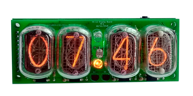
DA-2000 6-Digit Numitron Clock
This is a simple to build kit based on a Wemos micro controller, packed full of features and able to drive 6 Numitron tubes. Numitrons are long life filament displays and provide a warm glow and a restful display. The clock gets the time from an Internet NTP (Network Time Protocol) and is fully configurable via a browser.
This clock runs off a 5V DC USB power supply – an old one from a phone with a USB-B is perfect.
IV-9 6-Digit Numitron Clock
This is a simple to build kit based on a Wemos micro controller, packed full of features and able to drive 6 Numitron tubes. Numitrons are long life filament displays and provide a warm glow and a restful display. The clock gets the time from an Internet NTP (Network Time Protocol) and is fully configurable via a browser.
This clock runs off a 5V DC USB power supply – an old one from a phone with a USB-B is perfect.
All-In-One Clock for IN-14 / IN-8-2 / Z570M
This is a simple to build kit based on Arduino (Atmel ATMega micro controller), packed full of features for use with 6 IN-14 tubes. You don’t need to own an Arduino to use this kit! It is self contained and runs without an external Arduino board.
This kit is ideal if you want to make a traditional “6 in a row” eye catching clock in a custom case. You will need to add IN-14 tubes and an external power supply (9VDC centre positive, 5.5mm x 2.1mm barrel jack).
4-Digit Wemos Clock
A fully WiFi enabled clock using four IN-12 or IN-2 tubes. Fully configurable using a browser!
and the time is set from Internet atomic clock sources. The time also changes to respect daylight savings time. An external power supply (9VDC centre positive) is needed.
There is also a 3D printable case available for this clock for you to print at home!
ClassicWiFi Rev5
This is the new Classic Nixie Clock with an integrated ESP8266 WiFi module. This is our “Classic” board, but in a more compact form for the WiFi time provider. Note this this kit needs a small amount of SMD soldering!
You need to add the components, the tubes (any kind) and an external power supply (7.5VDC – 12VDC)
Modular Nixie Clock IN-14 tubes
This is a simple to build kit based on Arduino (Atmel ATMega micro controller), packed full of features and able to drive any combination of 6 tubes. It is the same as the “All-In-One” clock, but the tubes are mounted on removable tube holder boards.
This makes replacing a tube as simple as unplugging it and putting a new one in. You need to add IN-14 tubes and an external power supply (7.5VDC – 12VDC).
ClassicWiFi Rev6
This is the new Classic Nixie Clock with an integrated ESP8266 WiFi module. This is our “ClassicRev5” board, but updated to drive NeoPixels and tube decimal points, and to use a PIR or motion detector. Note this this kit needs a small amount of SMD soldering if you select the WiFi option!
You need to add the components, the tubes (any kind) and an external power supply (7.5VDC – 12VDC)
Single Decatron Clock (A-101 or OG-4)
A innovative and entertaining way of using a single Decatron to show the time, by rapidly animating the clock face on the round face of the Decatron. It is fully WiFi connected and supports a motion detector (PIR or microwave) to tun off the display when no one is there to see it.
You need to add the components, the Decatron (A-101 or OG-4) and an external power supply (7.5VDC – 12VDC)
Про подключение декатрона смотрим – Часы на цифровых лампах – там arduino dekatron shield Decatron A101 они дорогие десяток на 80 долл или 5000р и похоже почти все скупил. в Брянске не делают уже.
перевод будет
Separator LEDs/NeonsParts List:R381k or 270k (see note)R391k or 270k (see note)LED8LED 5mm (see note)LED9LED 5mm (see note)Neon1Neon indicator lamp(see note)Neon2Neon indicator lampP1Connect COM to HV or VCCNow that we have the tubes mounted, we can mount the separators. We do this after the tubesare mounted because now we can judge the height that the separators should be.Notes:•You can install either LEDs or neons as the colon indicators. There is a minor change to the components depending on which you choose.•For LEDs: You need to connect P1 “VIN” to “COM” and choose 1k values for R38 and R39. You need to take care of the polarity of the LEDs, following what is marked on the board.•For neons: You need to connect “170V” to “COM” and choose 270k values for R38 and R39. The polarity of the neons does not matter.•Be careful to adequately insulate the LED leads using some heat shrink or excess plasticsleeving.•Don’t use a pluggable “jumper” header for setting P1: Solder a wire between the pins you want to jump directly. If you use a header, someone later will want to change it.TroubleshootingThe separators do not light up.Make sure that you set the jumper P1 according to the separators you are using.Set to “VIN” for LEDs, or “170V” for neons.Front Panel componentsWhen all the components are installed, you are finished with the main build of the clock. You can now add the “front panel” components. These will usually be added on the outside of the clock case.SV24 pin connectorLDRLDRS1SWITCHThe switch connects to ground when closed. It uses the internal pull-up resistor provided by theAtmega on the input pin to pull the input to VCC when the switch is not closed.The switch is de-bounced in software, so practically any switch you want to use is suitable. A simple switch is provided in the kit, but you might want to substitute this switch with one that suits your case.The LDR forms a potential divider with R17. One leg of the LDR must be connected to the input pin, the other leg must be connected to GND.The LDR should be mounted in such a way that the flat face of the LDR is exposed to the ambient light. This will allow it to detect the ambient light and adjust the brightness for it.Please see the connection diagram in the schematics to understand how to wire the front panelcomponents.WiFi moduleParts List:R4010kR4110kR4210kR4310kC9100nFC10100nFC11220uF 10VQ72N7000 Q82N7000U178L33P22x4 Female HeaderWiFiPreprogrammed ESP-8266If you have the WiFi module, you need to install the level shifter components on the board. Thisprovides an interface between the 5V Atmel controller and the 3V3 ESP circuitry.Notes:•Be careful of the orientation of the polarity of the components Q7, Q8, U1 and C11•The ESP 8266 must be mounted so that the body of the board sits over the K155ID1, NOT pointing outwardsWarning!The ESP 8266 must point inwards to the board. It must not point outwards over the edge of the board.If you mount the ESP 8266 incorrectly, you will destroy it! The ESP 8266 does not have any key to make sure it cannot be mounted incorrectly, so you have totake care.RTC moduleParts List:RTCRTCSV3CONN_RTCThe RTC module is a traditional Real Time Clock module. Unfortunately we are no longer permitted to post the battery with the kit, so you will have to get your own. The battery you need to get is a CR2032, or a LIR20132 (rechargeable). You can mount the RTC module directly on the board, or as a separate board connected by flying leads.The markings on the board need to match up with the markings on the module. In particular, the VCC and GND need to be in the right orientation.The WiFi module has it’s own instruction manual. Please refer to that if you have the WiFi option.•The RTC module has two sets of contacts on it. You can use either the side with the pins on it or wire up the other side with flying wires. If you use the side with pins, you should carefully remove the two unused pins (see hint). If you use the contacts on the module, you should leave CONN_RTC off the board.•If you receive the connector header as a single strip, break off 4 pins for SV3.Hint: Trimming the extra pins on the RTC moduleONLY if you want to mount the RTC module directly onto the main board (you can also do it via flying leads), trim off the pins “32K” and “SQW” using a pair of precision side cutters.If you want to mount using flying leads, you can skip this step and use the four holes on the other side of the board.RTC Module with pins removedTroubleshootingIf not everything goes as you expect, please refer to the test steps during the construction and the associated troubleshooting tips. If that does not cover the problem you have, please see below. If you still can’t find the answer, contact us!TroubleshootingThe tubes flash (or blink) on and off.This could be a symptom that the external power supply can’t deliver the powerneeded to drive the circuit.On start up, the High Voltage generator needs to draw significantly more power than when it is running normally, and in some cases this might overload the external power supply.Try a different external power supply and see if the problem persists.TroubleshootingThe tube display brightness is not constant, and appears to “pulse” rapidly.This is a symptom that the High Voltage generator or the external power supply is overloaded.First perform a factory reset to make sure that no strange values have been left in the EEPROM.Next, check the value of the PWM On Timeconfiguration. Try increasing this until the brightness is constant, but be careful not to set the value too high. Thelonger the On Time, the more the MOSFET has to conduct current, and this will cause it to heat up. A good value for small tubes is 120-150, larger tubes may require 150-200.TroubleshootingThe display is too dim.Check if the auto-dimming is working. If the display does not change in low or high ambient light, your LDR does not appear to be working. Check the connections to the LDR.If the LDR is correct, perform a factory reset to make sure that no strange values have been left in the EEPROM.Check the LDR reading by pressing the button three times in quick succession when the clock is on. You should see a value between “01 00 00” and “09 99 00”. Changing the light conditions should change this value. It is normal that the value is not stable when it is in the middle of the range. We read the LDR many times a second, and it is unusual that two readings are identical.TroubleshootingThe display does not come on, but I do have a high voltage.Try pressing the button. If the display comes on, you probably have display blanking mode set. Check the configuration.Check the orientation of the opto-couplers.Check the LDR connection. In some cases, the dimming algorithm does not startup as expected when no LDR is present. Shine a bright light on the LDR.In some cases, a factory reset can help.TroubleshootingOne or more of the RGB LEDs will not go out completelyOne of the LEDs (either one of the R, G or B channels, or the TICK LED) does notgo out completely when it is configured to be dark or at the darkest point of the “pulse” flash.The FETs which drive the LEDs are very sensitive, and can pick up the stray voltages which are carried by excess flux on the board. Carefully clean with a non-scratching instrument between the three pins on the FET of the affected channel. Alternatively, use a solvent to remove excess flux.TroubleshootingThe MOSFET gets really hot.Try a factory reset. There is a setting about how hard the IRF740 should be driven “PWM On Time”. Perhaps the value has not been set properly. The defaultvalue should be OK most of the time, but depending on the tubes and power supply, this might need adjustment. The lower the value, the less power will be used and the less hot the MOSFET will run, but also the less power will be available to drive the tubes.Check the power supply. If the power supply is too “strong” (too much voltage or too much current capacity), the MOSFET will have to carry high currents. Try a different power supply. 9V and 500mA is ideal.Change the settings for the “PWM On Time”. Adjust it to be as small as possible without a loss of brightness. This also reduces the power consumption of the module: normally it should not consume more than 3W.TroubleshootingI can see some “ghosting”.“Ghosting” is where you can see a very faint image of another number at the same time as the one that should be shown. Some tubes are more sensitive than others, and depending on the construction and components, it might show up more.If you see ghosting, increase the “anti-ghosting” setting, but only to the point where the ghosting is no longer visible or irritating.The “anti-ghosting” setting decreases the overall brightness of the display slightly, and not all tubes (even of the same sort) need it, so anti-ghosting should only be used when there is a real need to use it.TroubleshootingThe clock sometimes just stops showing the digits.In especially noisy environments with clocks that have no grounding, external interference can cause the controller to lock up. In this case, please either put the clock in a grounded enclosure or select a higher quality power supply. (Poor quality power supplies don’t provide any path to ground).In extreme cases, there is a grounding point close to the crystal and you can ground the clock circuit.Programming the micro-controllerThe micro-controller comes preprogrammed. You don’t need to program it, but you might want to, especially if you want to change the code.You can update the micro-controller with a newer version of the software, or even create your own software, and load it onto the chip. We have gone to a lot of trouble to make this as easy as possible.Programming with an Arduino UnoWe supply the 328P micro-controller chips with a standard Arduino boot loader, so you don’t need to have a special programmer in order to update the software, a standard Arduino UNO is enough.To program the 328P, simply remove it from the clock board, and place it in the Arduino UNO. Then you will be able to program the controller as you would any other Arduino UNO, simply upload the software onto the controller. Put the 328P back into the clock board and you are done.You can also program the 328P micro-controller with a programmer, but you will lose the possibility to program in the Arduino UNO, unless you remember to burn the boot loader again.That’s it!One last thing: The controller used in the IN-14 All-In-One clock Rev is completely compatible with the Classic Nixie Clock module Rev2, Rev3 and Rev4. They can be interchanged without danger.:)Parts list / BOMHere is the list of the parts needed for the main board:#IDQtyValue1C5,C6222pF2LED9,LED82LED 5mm3C112.2uF4C3,C42220uF5LED2,LED7,LED6,LED5,LED4,LED36LED RAGB (common anode)6Q2116MHz7D1,D22UF40078IC2174141N9R214.7k10R11390k11R14,R7,R8,R28,R27,R26,R6,R1083k12R13,R12,R9,R11,R3,R19,R18,R23,R20,R21,R22,R24,R25,R29,R31,R32, R33,R34,R35,R36,R37,R4,R5,R15,R16271k13R38,R3921k for LEDs,270k for neons14R30,R17210k15IC31MEGA8-P 328P16OK1,OK2,OK3,OK4,OK5,OK66EL81717SV1,SV2,SV334 pin header18Q3,Q4,Q532N700019Q61MPSA4220C7,C2,C83100nF21LED11LED 3mm22L11100uH23IC11780524Q11IRF64025N2,N5,N4,N3,N6,N16IN-1426CON_11Barrel JackParts needed for the optional WiFi module:#IDQtyValue1R40, 41, 42, 43410k2C9, C102100nF3C111220uF 10V4Q7, Q822N70005U11AP1117-3V36P212x4 Female HeaderRevisions:V0001: 12Jan2018: New manual for Revision 3V0002: 05Dec2018: Correct External Components drawing, thanks Kent!V0003: 14May2020: Correct Wifi BoM, and separators section.
я не перевожу – на поиск этой комплектухи у нас уйдет месяца 2 – без поездки к Павелецкому в крупную компанию будет трудновато да и туда доставят от 500 штук за месяц. Ардуино уно делается с помощью кристалла atmega328p – подсоединить к wileem eprom или к другой ардуинке и прошить загрузчик ( купить на радио рынке или Али готовые ). Для опытов нужен комп нормальный – можно ноутбук, параллельный порт не обязательно. Держу для программатора 2 системника года 2008 со всеми портами – на одном материнка asus p5w dh deluxe он покупался за 3000 американских с корпусом и видеоплатой. Примерно 2006 года , там памяти много, 16 вроде и винда 10-ка установилась, а диск пришлось поменять – нового типа ssd не стал работать но запустился прекрасно toshiba на 3 терабайта ( найти в крупном розничном магазине а то сейчас эпидемия – компьютерщики заразились майнером chia , я не очень поддерживаю, этот диск не ходовой). Хорошо подойдут советские ex-ussr детальки, но они сейчас дороже так раз в пяток – оказалось делали очень хорошо, да еще буковки военной приемки. вариант анодных ключей кт3157а кт940 (mpsa92 mpsa42).
програмка на ассемблере часы ( буду разбирать еще прошивку с какой то – залоченой – платы, раньше увлекались)
;**************************************************************************
; Jon's Mods 12/2006 for B7971 alphanumeric nixie tube
; Earl's Mods 7/2005 for standard nixie tube driven by Port A and Port B
; Original program was David Tait's CLOCK.ASM
;
; Displays time on a single B7971 Nixie display.
; Timing Source: 4 MHz crystal

; A B7971 Nixie display is attached as follows:
;
;	PIN	SEGMENT			B7971 PIN #
;	RB0       1			    8
;	RB1       2			    5
;	RB2       3			    6
;	RB3       4			    9
;	RB4       5			    14
;	RB5       6			    15
;	RB6       7		  	    12 (SEE NOTE 1)\
;	RB7       8			    7		    } Both active = pin 1, 10 on
;	RA0	  11			    16 (SEE NOTE 1)/
;	RA1	  9			    3  (SEE NOTE 2)\
;	RA2	  14			    4  (SEE NOTE 2)/ Both active = pin 17 on
;
;	RA3 Chime Output
;	RA4 Switch Input
;
; * Note 1:
; RB6 and RA0 feed into logic gate system, RB6 feeds segment 7 via NOR
; and RA0 feeds segment 11 via NOR. When both RB6 and RA0 are active, segment 10/13 on.
;
; * Note 2:
; RA1 and RA2 feed into logic gate system, RA1 feeds segment 9 via NOR
; and RA2 feeds segment 14 via NOR. When both RA1 and RA2 are active, segment 12 on.
;
; Each output is connected via a resistor to a transistor base.
; The common anode is connected to high voltage (200-300V) through a resistor.
; Holding button down during power up runs a Nixie Test program.
;
; The time is displayed digit by digit over a four second period
; every 10 seconds and the display is blank otherwise.
;
; A normally open switch is connected from RA4 to GND via a 470 ohm
; resistor; no pull-up resistor is needed as an internal weak pull-up
; is enabled by the program.  To set the clock press the switch when
; the appropriate digit is displayed; the digit can then be incremented
; by pressing the switch repeatedly.  If the switch is open for about
; 2 seconds the clock display is restarted allowing another digit to be
; changed.  It is up to the user to put in sensible times as no checking
; is done by the program.
;
;**************************************************************************
	processor	16f84
	include		<p16f84.inc>
	__config	_XT_OSC & _WDT_OFF & _PWRTE_ON

	ERRORLEVEL      -302    ; suppress bank selection messages

PCL     EQU     2               ; registers are defined here to make this
STATUS  EQU     3               ; program self contained.
PORTA   EQU     5
PORTB   EQU     6
INTCON  EQU     0BH
TRISA   EQU     85H
TRISB   EQU     86H
OPTREG  EQU     81H

C       EQU     0               ; bits in STATUS
Z       EQU     2
RP0     EQU     5

T0IF    EQU     2               ; bit in INTCON


; Below are ticks for 4 MHz crystal

TCK0    EQU     .122
TCK1    EQU     .123
TCK2    EQU     .121
TCK3    EQU     .123
TCK4    EQU     .124
TCK5    EQU     .125
TCK6    EQU     .125


	CBLOCK  0CH             ; define variables required

	TICKS                   ; decremented every tick (9.15 ms or 8.19 ms)
	SEGS                    ; one bit per segment
	SEC
	SEC10
	MIN
	MIN10
	HOUR
	HOUR10
	FRAME                   ; used to decide when to display time
	HHMM                    ; one bit per digit displayed
	COUNT                   ; scratch register
	DIGIT                   ; last digit displayed
	CHIME			; Number of chimes needed
	ENDC


	;*********************************;
	;         Initialization          ;
	;*********************************;

	ORG     0

INIT    CLRF    SEC
	CLRF    SEC10
	CLRF    MIN
	CLRF    MIN10
	CLRF    HOUR
	movlw	D'1'
	movwf	HOUR10
	CLRF    FRAME
	CLRF    PORTA
	CLRF    PORTB
	CLRF	CHIME
	BSF     STATUS,RP0      ; select register bank 1
	CLRF    TRISB		; all of port B are outputs
	MOVLW   10H
	MOVWF   TRISA           ; only RA4 is an input
	MOVLW   4
	MOVWF   OPTREG          ; assign prescaler (1:32) to TMR0
	BCF     STATUS,RP0      ; reselect bank 0

	BTFSS   PORTA,4         ; switch on RA4 open?
	GOTO    TEST         	; no, go to test mode
	;*********************************;
	;          Main Program           ;
	;*********************************;

MAIN    CALL    CLOCK           		; real-time clock algo called every second
		CALL    SHOW            	; display the time
		MOVF	CHIME,F			; check if chimes needed
		BZ	WAIT			; No Chime now
		BSF	PORTA,3			; Chime on RA3
		DECF	CHIME,F
WAIT    BTFSS   INTCON,	T0IF     		; wait for TMR0 to roll over
		GOTO    WAIT
		CLRF    INTCON
		CALL    CHKSW           	; check for button press
		MOVF	TICKS,W
		XORLW	D'20'			;Check for 20 ticks
		BTFSS	STATUS,Z
		GOTO	J1
		CLRF	PORTB			;Turn off Display at 100/120 ticks
		CLRF	PORTA
J1		DECFSZ  TICKS,F
		GOTO    WAIT
		GOTO    MAIN            	; get here every second


	;*********************************;
	;  Convert digit to segment form  ;
	;*********************************;

SEGTAB  ANDLW   0FH
	ADDWF   PCL,F

	DT      0xFC,0x02,0xD1,0xB1,0x67,0x96,0x9E,0x80,0xFF,0xF1,0x00 ; Port B lookup table

SEGTABA  ANDLW   0FH
	ADDWF   PCL,F

	DT      00h,01h,01h,04h,00h,02h,02h,05h,00h,06h,00h ; Port A lookup table

	;*********************************;
	;  Real-time clock algorithm      ;
	;*********************************;

CLOCK   MOVLW   TCK0            ; increment digits as appropriate
	MOVWF   TICKS           ; and define number of ticks per
	INCF    SEC,F           ; second for next second
	MOVF    SEC,W
	SUBLW   9
	BTFSC   STATUS,C
	 RETURN

	MOVLW   TCK1			;per 10 sec
	MOVWF   TICKS
	CLRF    SEC				;clear seconds, add 10 seconds
	INCF    SEC10,F
	MOVF    SEC10,W
	SUBLW   5				;check for a 6
	BTFSC   STATUS,C
	 RETURN

	MOVLW   TCK2			;per min
	MOVWF   TICKS
	CLRF    SEC10			;clear 10sec, add 1 minute
	INCF    MIN,F
	MOVF    MIN,W
	SUBLW   9				;check for 10
	BTFSC   STATUS,C
	 RETURN

	MOVLW   TCK3			;per 10 minutes
	MOVWF   TICKS
	CLRF    MIN				;clear minute, add 10 minute
	INCF    MIN10,F
	MOVF    MIN10,W
	SUBLW   5
	BTFSC   STATUS,C
	 RETURN

	MOVLW   TCK4
	MOVWF   TICKS
	CLRF    MIN10
	MOVF    HOUR10,W
	SUBLW   1
	BTFSC   STATUS,C
	 GOTO   INCHR
	INCF    HOUR,F
	MOVF    HOUR,W
	SUBLW   3
	BTFSC   STATUS,C
	goto SETCHIME

	MOVLW   TCK6
	MOVWF   TICKS
	CLRF    HOUR
	CLRF    HOUR10
	goto SETCHIME


INCHR   INCF    HOUR,F			;Add to single digit hour
		MOVF    HOUR,W
		SUBLW   9		; did it go from 9 to 10 ?
		BTFSC   STATUS,C
		goto SETCHIME		; no, it's  less than 10

		MOVLW   TCK5		;deal with 9 to 10 carry
		MOVWF   TICKS		;each 10 hour
		CLRF    HOUR
		INCF    HOUR10,F
		GOTO SETCHIME

SETCHIME 	MOVF	HOUR,W		;On hour change set chimes
		MOVWF	CHIME
		MOVF	HOUR10,F
		BZ	J2
		MOVLW	D'10'
		ADDWF	CHIME,F
J2		RETURN
	;*********************************;
	; Displays the time digit by digit;
	;*********************************;

SHOW    CLRF    HHMM
		INCF    FRAME,F         ; increment place in frame
		MOVF    FRAME,W
		SUBLW   D'06'			; Display cycle time
		BTFSS   STATUS,C
		CLRF    FRAME
		MOVF    FRAME,W
		XORLW   1
		BTFSC   STATUS,Z
		GOTO    DHOUR10        ; display 10s of hours when frame is 1
		XORLW   1^2
		BTFSC   STATUS,Z
		GOTO    DHOUR          ; display hour when frame is 2
		XORLW   2^3
		BTFSC   STATUS,Z
		GOTO    DMIN10         ; display 10s of mins when frame is 3
		XORLW   3^4
		BTFSC   STATUS,Z
		GOTO    DMIN           ; display mins when frame is 4
		MOVLW   H'00'              ; otherwise blank display
		MOVWF   PORTB
		MOVLW   H'00'
		MOVWF   PORTA
		RETURN

DHOUR10 BSF     HHMM,3
		MOVF    HOUR10,W
		BTFSS	STATUS,Z		;check for leading zero
		GOTO    DISPLAY
		RETURN					;skip display of zero

DHOUR   BSF     HHMM,2
		MOVF    HOUR,W
		GOTO    DISPLAY

DMIN10  BSF     HHMM,1
		MOVF    MIN10,W
		GOTO    DISPLAY

DMIN    BSF     HHMM,0
		MOVF    MIN,W           ; falls through to DISPLAY


	;*********************************;
	;       Displays digit in W       ;
	;*********************************;

DISPLAY MOVWF   DIGIT           ; save number to be displayed in DIGIT
	CALL    SEGTAB          ; call bit allocation table
	MOVWF   PORTB           ; and display bits for port B
	MOVF	DIGIT,W
	CALL	SEGTABA		; call bit allocation table
	MOVWF   PORTA           ; and display bits for port A
	RETURN


	;*********************************;
	; Checks for a switch press and   ;
	; updates digit if displayed      ;
	;*********************************;

CHKSW   BTFSC   PORTA,4         ; switch closed on RA4?
		RETURN                 ; no
		MOVF    HHMM,F
		BTFSC   STATUS,Z        ; digit displayed?
		RETURN                 ; no

INCDIG  INCF    DIGIT,F         ; DIGIT is the currently displayed number
		MOVF    DIGIT,W
		SUBLW   9
		BTFSS   STATUS,C
		CLRF    DIGIT
		MOVF    DIGIT,W
		CALL    DISPLAY
		CALL    DELAY           ; wait for switch to settle
CHKSW0  BTFSS   PORTA,4         ; switch open?
		GOTO    CHKSW0         ; no
		CALL    DELAY
		BTFSS   PORTA,4         ; still open?
		GOTO    CHKSW0         ; no
		MOVLW   D'20'
		MOVWF   COUNT
CHKSW1  BTFSS   PORTA,4         ; switch open?
		GOTO    INCDIG         ; no
		CALL    DELAY
		DECFSZ  COUNT,F
		GOTO    CHKSW1
		MOVF    DIGIT,W         ; switch was open for around 2 secs
		CLRF    FRAME
		CLRF    SEC10
		CLRF    SEC
		BTFSC   HHMM,3          ; update correct digit
		MOVWF  HOUR10
		BTFSC   HHMM,2
		MOVWF  HOUR
		BTFSC   HHMM,1
		MOVWF  MIN10
		BTFSC   HHMM,0
		MOVWF   MIN
		GOTO    MAIN            ; restart the program


	;*********************************;
	; Delay used by switch routine    ;
	;*********************************;

DELAY   MOVLW   D'12'           ; roughly 100ms delay
		MOVWF   TICKS
DEL1    BTFSS   INTCON,T0IF     ; wait for TMR0 to roll over
	 	GOTO    DEL1
		CLRF    INTCON
		DECFSZ  TICKS,F
	 	GOTO    DEL1
		RETURN

TEST	CLRF	COUNT			;exercise Nixie by cycling through
		MOVF	COUNT,W			;all numbers
		CALL	DISPLAY
		CALL	DELAY
		CALL	DELAY		;1 second delay
		INCF	COUNT,F
		MOVF	COUNT,W
		XORLW   D'10'			;Test for 10
		BTFSS   STATUS,Z
		GOTO    TEST+1
		GOTO	TEST   		;Reset COUNT to 0
		END
програмка на бейсике (pic basic)
пограмма часов на другой плате . Без статики – но там выбираются 3 выхода на аноды ламп – каждый на 2 и 2 дешифратора К155ИД1, подобрал же 185 вольт для всех ИН1 без засветов лишних. Будет 4 штуки ИН18 – самые большие из доступных и у них такие же резисторы как у ИН1, 15 килоом или 18 , 175 -195 вольт.
////////// Hardware outputs //////////
//This clock is 2x3 multiplexed: two tubes powered at a time.
//The anode channel determines which two tubes are powered,
//and the two SN74141 cathode driver chips determine which digits are lit.
//4 pins out to each SN74141, representing a binary number with values [1,2,4,8]
byte binOutA[4] = {2,3,4,5};
byte binOutB[4] = {6,7,8,9};
//3 pins out to anode channel switches
byte anodes[3] = {11,12,13};
полностью код программы будет с изменениями – arduinix 6 , 4, https://github.com/isparkes?tab=repositories https://github.com/isparkes/ArdunixNix6 RLB Design’s плата UNDB https://github.com/clockspot/arduino-clock это оригинал. Я хорошо разогнал под статический дисплей програмку и яркость не потерялась и не моргает – 56 больших циклов в секунду : убрал настройку последовательных регистров в подпрограмму, все через ShiftOut библиотеку. Это на моей страничке – есть в записи Часы на цифровых лампах. Не моргает, свет яркий, 3 эффекта работают включая затухание плавное и смена сразу 2-х цифр, на определенное время включаются 53-56 раз в секунду. Взял еще один эффект – и сделал – сменяемая цифра _сгорает_ со вспышкой – надо в конфигурации включить режим fade настройка 11.
добавляю устройство фонарик – используется открытая матрица led cob на 10 ватт на хорошем радиаторе – как бы катушка намотана и ее обмотка позволяет 5 ампер снять. Выпрямитель конечно будет Шоттки на 40А от блока питания.
штука вообще инопланетная – часы -включаются кнопочкой на секунд 20, 5 ламп ИН12 , мощный фонарь и батарейка плоская (от ноутбука) – для вылазок на природу пойдет, не хватает только зеленого лазера * его аргонка требует мощности неслабой лгн406 например 380 вольт ампер 100 вот на дискотеке включали давно было не вру на секунды, пожарка не понадобилась.
подсветка из одного led cob – то есть это на самом деле кристалл на котором 9 светодиодов по 1 ватту, у него характеристика – 12 вольт питание 3 Ома ток 0,4 напряжение на сборке 9,8 – 50 процентов а 2 ома ток 0,6 и 10,4 в – не проверял больше а то погорит : 300 mA на светодиод и 900 на сборку может и можно но яркости не прибавит а дым скорее всего пойдет. 3,6 вольта на каждый кристаллик это на пределе, такие же только из 3 кристалликов ставятся на светодиодную ленту, там превышать напряжение нельзя здохнут. ( а из 50 штук по 0,1 ватта только чуть желтоватые лампочка – намного ярче на глазок). Снимок из пещеры на Imgur – это вот такой фонарь из 50 кристаллов как прожектор, он 4 ватта всего.
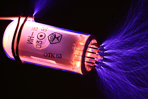
проверка лампочки ( есть видео на ю тюбе – поиск – проверка ламп и декатронов) просто приблизить к Катушке Теслы. Поле высокой частоты зажигает неон внутри лампы и не только неон – голубым загораются наполненные водородом тиратрон и стабилитрон газовый, а это нужно 1000 вольт. А они там есть. Катушка Теслы есть на страничках – она не совсем резонансная но близко – на частоте удвоенной от резонанса на самом деле – особенность транзистора КТ817 при токе 2 ампера а частота 6 мегагерц, 16 вольт. Эффект начинается при большой катушке от 1700 а если еще больше то от 145 – 150 килогерц. Кстати ВЧ разряд не бьет током но может обжечь – уколоть палец.
