Add unit prefix as a suffix to the number, for example: 1M. This calculator will automatically add unit prefixes where appropriate. They will be added as a suffix to the calculated value.
For example, 0.0012 V (1.2 mV) may be displayed as
1.2 mV, 1.2mV or 1.2m [V] depending on output field
format.
Supported unit prefixes:
f
p
n
u
m
c
k
M
G
T
P
femto
pico
nano
micro
milli
centi
(none)
kilo
mega
giga
tera
peta
10-15
10-12
10-9
10-6
10-3
10-2
100
103
106
109
1012
1015
For squared quantities (for example areas), only the following suffixes are supported: u, m, c, k, M
For convenience, u is used instead of μ.
Version 0.99b-WIP (20220726). Using KaTeX 0.11.1 for equations. This tool is provided without any warranty. Use at your own risk.
Ohm's law
Enter two quantities, the third one will be calculated R=IV
Power (for DC circuits)
Enter two quantities, the third one will be calculated P=V⋅I
Power (for AC circuits)
Enter two quantities, the third one will be calculated P=V⋅I⋅cos(ϕ) Q=V⋅I⋅cos(ϕ) ∣S∣=Vrms⋅Irms
E6/E12/E24 series (IEC 60063 standard)
LED resistor calculator
R=ILEDVin−VLED
Capacitance, 3 digit code conversion
Enter either capacitance or code, the other value will be auto-calculated
Allowable range: 10pF to 99mF (although capacitors bigger than 10uF usually aren't marked this way)
Tolerance letter
B
C
D
F
G
J
K
M
Z
Tolerance value
±0.1pF
±0.25pF
±0.5pF
±1%
±2%
±5%
±10%
±20%
+80, -20%
Capacitor reactance
Enter two quantities, the third one will be calculated XC=2⋅π⋅f⋅C1
Inductor reactance
Enter two quantities, the third one will be calculated XL=2⋅π⋅f⋅L
RLC circuit impedance
XL=2⋅π⋅f⋅L XC=2⋅π⋅f⋅C1 Serial: Z=R+j⋅2⋅π⋅f⋅L−2⋅π⋅f⋅Cj ∣Z∣=R2+(XL−XC)2
If XL>XC, then φi=−arccos(∣Z∣R)
If XL<XC, then φi=arccos(∣Z∣R) Parallel: ∣Z∣=R21+(XL1−XC1)21 φi=−arctan(XL1−XC11R)
Resonant frequency
Enter two quantities, the third one will be calculated. fr=2⋅π⋅L⋅C1
Critical damping (aperiodic) resistance for RLC circuit, LC characteristic impedance
Input quantities: Q<0.5 (Q=Z0R for parallel circuit, Q=RZ0 for series circuit, Z0=CL)
Capacitor peak dv/dt, peak current
Enter two quantities, the third one will be calculated. Imax=C⋅max(dtdv(t))
Capacitive dropper - average rectified current, sine input
This calculator assumes a sine wave input + a constant DC load
voltage. For reasonable accuracy, set the limiting resistor value to
≤1/10 of XC at the selected frequency.
Using the resistance calculated through the classic XC
calculation to calculate the current gives the RMS current value, not
the average rectified value, will give inaccurate current & power
(~10% error) with a constant voltage load.
The equation was obtained by integrating the average current
(i(t)=C*dv/dt) using a "cut" sine wave according to the voltages, and
was verified using LTspice.
This calculator uses the "10-degree rule" (doubling the lifetime
with every 10°C temperature drop - compared to the lifetime at the rated
max. temperature given the specified ripple current and voltage - k1=2, k2=10)
for "classic" liquid electrolytic/hybrid capacitors and the "20-degree
rule" (10 times the life with a 20°C temperature drop - k1=10, k2=20).
The estimation won't be particularly accurate at temperatures under
40°C. Also, the lifespan will be much lower at higher currents than
specified, at lower currents, it will be higher - refer to manufacturer
normograms/datasheets/app-notes for such cases, or the paragraph below.
Optional input - Alternatively, ΔTC-norm (core
self-heating over ambient temperature at rated current, depends on exact
capacitor, can be about 5-20 degrees), the rated RMS current at the
specified frequency, and the actual load current can be used to
calculate lifespan at different currents.
The equations and results were checked against application notes
and datasheets provided by big capacitor manufacturers such as Rubycon,
TDK or Capxon and were found to be reasonably accurate and universal.
No endorsement of this calculator by any of these companies is implied.
This calculator should be used as a reference, for guaranteed values,
check data provided by the manufacturer.
Enter two quantities, the other one will be calculated. maxdtdv(t)=2⋅π⋅f⋅Vm
Sine wave amplitude ↔ RMS
Enter one quantity, the other one will be calculated. Vpk=2⋅Vrms
Rise time, bandwidth
Select encoding/use, enter one quantity, the other one will be calculated. Assuming first order system, 3 dB permissible attenuation at max. frequency, 10% to 90% rise time, some rounding is done. NRZ/RZ = (Non) Return-To-Zero tr=BW0.35(RZ),tr=BW0.7(NRZ)
RC low-pass filter
Enter three quantities, the fourth one will be calculated.
RC high-pass filter
Enter three quantities, the fourth one will be calculated.
Power ratio / decibel conversion
Input one quantity, the other one will be calculated. ratio(dB)=10⋅lg(ratio)
Voltage ratio / decibel conversion
Enter one quantity, the other one will be calculated. ratio(dB)=20⋅lg(ratio)
Power / dBm conversion
Enter one quantity, the other one will be calculated. P=10(0.1⋅(PdBm−30))
Inductor current rise
ΔI=LV⋅ΔT
Toroid inductance/turns
For more complex/universal calculations with more possible
parameters, use "Gapped or ungapped inductor/transformer saturation
current & inductance".
Enter either inductance or turn count, the other quantity will be automatically calculated. L=π⋅dμr⋅μ0⋅N2⋅S
Inductance/turns
This calculator assumes a reasonably high μ and a closed magnetic circuit.
For more complex/universal calculations with more possible
parameters, use "Gapped or ungapped inductor/transformer saturation
current & inductance".
Enter four quantities, the remaining one will be automatically calculated. L=lN2⋅S⋅μ0⋅μr
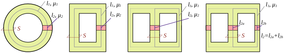
Gapped or ungapped inductor/transformer, inductance and saturation current
For ungapped inductors, leave l2=0, μr2=1. Relative permeability of air is 1. Rm1=μ0⋅μr1⋅Sl1, Rm2=μ0⋅μr2⋅Sl2, Rm(tot)=Rm1+Rm2l(tot)=l1+l2, μeff=S⋅Rm(tot)l(tot)L=Rm(tot)N2, Isat=N⋅μeffl(tot)⋅BmaxFm=N⋅I, Φ=Rm(tot)Fm=B⋅S, L=IΦ, B=μ⋅H, H=lN⋅I
Capacitor voltage rise
ΔV=CI⋅ΔT
Capacitance
Enter three quantities, the other one will be calculated. C=lS⋅ϵr⋅ϵ0
Capacitor charge
Enter five quantities, the other one will be automatically calculated τ=R⋅C ttotal=τ⋅ln(Vsupply−VfinalVsupply−Vinitial) Vfinal=Vinitial+(Vsupply−Vinitial)⋅(1−e−t/τ)
Capacitor discharge
Enter four quantities, the other one will be automatically calculated τ=R⋅C Vfinal=Vinitial⋅(1−e−t/τ)
Capacitor stored energy
Enter two quantities, the third one will be automatically calculated E=0.5⋅C⋅V2
ESR ↔ tan δ
Enter the frequency, capacitance and either ESR or tan δ ESR=XC⋅tan(δ)
A duty cycle lower than 50% can be achieved by connecting a diode in parallel to R2. Vctrl= Control voltage (100%ofVCC)
No diode parallel to R2:
Tlow=ln(2)⋅R2⋅C
No diode parallel to R2:
Thigh=(ln(1−Vctrl1−0.5⋅Vctrl)⋅(R1+R2)⋅C
Diode parallel to R2:
Thigh=(ln(1−Vctrl1−0.5⋅Vctrl)⋅R1⋅C (diode drop is neglected) T=Tlow+Thigh f=T1 Duty(%)=100⋅TThigh
Monostable 555 period
Vctrl= Control voltage (100%ofVCC) T=−ln(1−Vctrl)⋅R⋅C
IR(S)2153(1)(D) frequency
f≈1.4⋅(Rt+75)⋅Ct1
UC3842, UC3843, UC3844, UC3845 frequency
The result may not be accurate if the timing resistor is lower than 5kΩ fosc≈Rt⋅Ct1.8
TL494/KA7500 frequency
fosc≈Rt⋅Ct1
Voltage regulator feedback
Enter three quantities, the other one will be auto-calculated Vout=Vref⋅(R1R2+1)
Chip
Voltage
LM317T
1.25V
MC34063
1.25V
LM2576-ADJ
1.23V
LM2596-ADJ
1.23V
UC384x (VFB)
2.5V
MOSFET, IGBT, diode switching loss calculator, SEMIKRON AN1403 method
Calculate conduction loss separately (approximately IRMS*resistance for FETs, or IAVG for diodes and IGBTs). Gate drive loss is neglected.
The "scaling factor" KS is not included in the Semikron
PDF. According to simulations, if a MOSFET has a certain switching loss
with certain gate drive resistance (external+internal gate resistance)
and it is doubled, the loss will be also roughly doubled (Ks≈2). The
MOSFET coefficients also aren't present in the original PDF and were
determined empirically through simulations. Switch and diode losses must
be calculated separately. Calculate turn-on and turn-off losses separately and add the results. Diode turn-on losses are usually neglectable compared to conduction and turn-off. Psw=f⋅Eref⋅(IrefI)KI⋅(VrefV)KV⋅(1+KT⋅(T−Tref))⋅KS
MOSFET switching loss estimation
Calculate conduction loss separately (approximately IRMS*resistance for FETs, or IAVG for diodes and IGBTs). Switch and diode (internal diode - if it conducts) losses must be also calculated separately. Don't forget to add prefixes, times are usually in nanoseconds. The gate resistance effect (tr, tf depend on Rg) calculation is usable only if the gate drive voltage is close to the reference. If
only a light load is switched at a high frequency, it might be a good
idea to add the D-S capacitance discharge loss. However, this
capacitance might also reduce turn-off loss. The coefficients were
determined theoretically by linearizing the waveform and integrating
instantaneous power through the switching times while rising/falling.
Select "Custom" in dropdown menus to use custom Kl. Kg=Rg_int+Rg_ext_refRg_int+Rg_ext Ecap=0.5⋅Coss⋅Vds_off2 Eswon=Kc⋅Kg⋅Kl⋅tr⋅Vds_on⋅Id_on Eswoff=Kc⋅Kg⋅Kl⋅tf⋅Vds_off⋅Id_off Psw=f∗(Esw_on+Esw_off+Ecap)
MOSFET/IGBT gate drive loss
Pgd=f⋅Vgs_s⋅Qg
MOSFET, IGBT, diode, resistor conduction loss calculator
Enter only quantities related to the waveform and part type This function is quite complex and not well tested yet, implemented only based on theory with few simulations, USE AT YOUR OWN RISK.
For simplicity, constant voltage drop + already rectified signal is
assumed for diodes, constant resistance is assumed for MOSFETs. PD,IGBT≈Vdrop⋅IARV PMOSFET≈R⋅IRMS2 Table
Multiply RMS value of sine/triangle by sqrt(2) to get RMS value of half-rectified sine/triangle