Туристические маршруты
Всякие разности

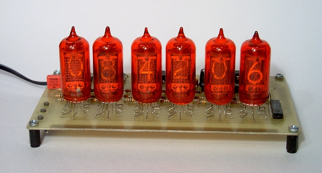
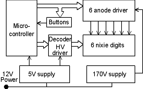
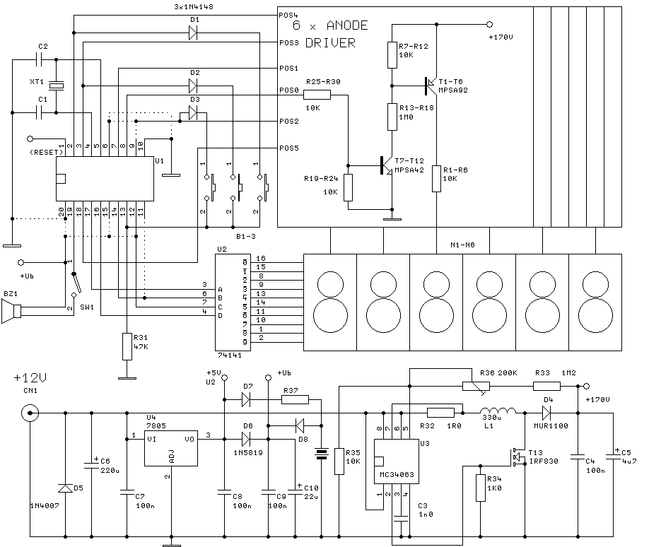
Более простой вариант. Сначала найти надо лампы а то их опять скупили. Some time ago I was poking in my box of old components. I was searching something else, but I stopped when a few of nixies came up into my hand. Once upon a time (a long, long time ago) I have mined them from an old calculator. I remember... Thirty years ago 6 nixies were a small treasure. He who was able to construct nixie clock with TTL logic, he befit into category "old hand". Nixie light was somehow warmer. A few minutes later I was tuned in the mood of vacuum tubes. Curiosity came to my mind. Would these old bulbs have operated? Now you can construct such clock easy. Just take one microcontroller... Because I was interested in possibility of microcontroller programming with high-level language in the same time, I decided to play a little. I tried to construct easy nixie clock. The clock will have 6 digits and time setting will be done by means of a few buttons. I will try to use the most common types from widely used microcontroller families of miscellaneous producers. I will write the program in C language. Nixies need high voltage for operation. I wanted to avoid dangerous mains line voltage. The supply voltage for the clock must be safe 12 V. As the main target of the construction was toy, this instruction is not subtle construction with mechanical details and specified case. You can modify the clock to your taste and qualification. The described clock accomplishes these results: The multiplex mode is natural solution for device with 6 digit display. TTL IC 74141 ensures BCD decoder and high voltage driver for individual digits. Perhaps it will be difficult to come by 1 piece of it (I don't know if 74141 is produced still). But if you discovered nixies, 74141 could be near :-). In time of TTL logic fame the 74141 was almost exclusive alternative. So try to find one. Nixie need voltage about 170 V. It would be useless to design special circuit for voltage converter. There is a lot of IC for step-up (boost) converters. I selected low cost and widely available MC34063. The converter circuit is almost copied from data sheet. Just only power switch is strengthened by T13. Internal switch is not suitable for such high voltage. I use choke coil as inductor for converter. Diameter is 8 mm and length is 10 mm - see the picture. Efficiency of the converter is good and output voltage is relatively safe. The output voltage decreased to 60V at output current 5 mA. R32 is current-sense resistor. Power supply for logic is linear regulator U4. There is a place for reserve accumulator (3.6 V - NiMH or NiCd) in the schematic and on the board. Diodes D7 and D8 are Schottky type and R37 must limit charge current in compliance with accumulator. Accumulator, D7, D8 and R37 are not necessary if your clock will serve just for fun. The final schematic diagram is here: The component bill is here, PCB is here... Actually every microcontroller with appropriate number of pins can control such simple device. Minimal number of pins is: All microcontroller manufacturers design specific families and types. Pin configurations of individual types are various. I tried to design universal PCB for several microcontrollers. There is 20 pin socket on the board. You can adapt it for miscellaneous microcontrollers with a change a few wire jumpers. Types tested by me are listed below. You can try additional types. Processor option is advantageous. Amateur of electronics applies one microcontroller family usually and his hobby corner is equipped with programmer and tools for this family. It can be problem to use microcontrollers from other manufacturers. You can choose your favourite processor below. Ready for use is type, source and binary code, development tools and programmer. If you compare source code for individual microcontrollers you can see that code is very similar. Differences are in port access, function definition for interrupt and in HW dependent part. Source code consist of 2 sections. Function main() is responsible for port setting and starts timer for interrupt. After that it scans pressing of buttons and sets appropriate time or alarm. There is compared time with alarm in the main loop and handled buzzer as well. The second part is timer interrupt routine. Interrupt is called over every millisecond (it depends on timer capabilities). Interrupt routine increments time variables and drives display digits. The status of buttons is tested also. Start component mounting and setting in operation with power supply. Mount U4 and components around. Check voltage 5 V for U2 and cca 4,6 V for U1. The next step is high voltage converter mounting. Use R36 to set the output voltage to 170 V. If the range of trimmer is insufficient change the value of R33 slightly. Insert U2, transistors and resistors for anode drivers and nixies. Connect U2 inputs to GND and in sequence separately connect R25 - R30 to +Ub. The nixie in this position would light. As the last HW test connect pin 19 of U1 to GND - buzzer will beep. You can find source and compiled program for microcontroller in the appropriate ZIP file. After microcontroller is programmed check carefully every pin of U1 position and fill up needed wire jumpers and tin junctions. See the pictures for microcontrollers above. If the microcontroller is correctly programmed and connected the clock would start to operate. You can set the time and alarm. Warning! There is one more button position on PCB (spare button for future expansion :-). Check clock accuracy. If the accuracy is out of your expectation change slightly value of C1, C2 (add small parallel capacitor or choose new value for C1, C2). Clock accuracy will improve. Small 8bits processors are ready for high level language programming already. C language is not primary intended for small microcontrollers. But you can use it very well for common applications. An assembler will be better for difficult tasks with time critical locking or with maximum load of processor. Free or limited version of C language SW tool will be sufficient for most hobby constructions. Programming in C is similar for various microcontrollers. You have to know hardware functions (registers and function of peripheral) of your favourite type. Be careful in bit manipulation - C language is not equipped for specific bit operations - e.g. see source code for ATtiny. Are you finished? So, tune into the mood of vacuum tubes and see... ... old times are coming... 🙂 The nixie clock design is ready for your modifications. Čestmír Hýbl made his own program modification for ATtiny2313. His page is here. Users of other microcontrollers can draw inspiration from his source code. If you prefer counting your life in 12-hour cycles (and you want to know if your lunch is before you - AM; or you are after lunch - PM :-), then see Adam Jacob's modification. [download id="87458"] Adam Jacobs thinks, that not only nixies are adorable. That's why he modified clock for other display. You can download his modification for vacuum fluorescent display here.[download id="87439"][download id="87458"][download id="87455"][download id="87452"][download id="87448"] * для irf840 обязательно добавить драйвер затвора на 2 транзисторах просто усилитель комплементарная пара прямо без резисторов в разрыв провода управления затвором. Снизит потребляемую мощность в 2 раза а нагрев ключа раза в 3. во вложениях есть прошивки. по этим часам в Китае сделали очень красивый набор для распайки и сборки - купите его за 800р. Есть 2 варианта, со светодиодным индикатором и на лампах (7500р) и без ламп 1900р что может быть выгоднее - за 2000 с пересылкой пришлют с радиорынка или из Ровно Ривно с Украины. пишу с телефона и может с кодировкой проивается ошибка. Не под землей но далековато. Более сложный вариант в статике и с 6-ю микросхемами К155ИД1 - их из Минска привезли коробку они оказывается на заводе еще делаются! И с 3-мя штуками 74НС590. Делаю маленькую платку с ds3231 и 3-мя нс590 - чтобы эти довольно нежные чипы были подальше от высокого. Просто прорезал фольгу по линейке, взял обломок полотна ножовки. Чипы то поверхностного монтажа. А у ИД1 можно ножки позагибать - не стал все таки дырочки просверлил 0.6 мм. Навскидку это за вечер другой ну если надо будет несколько то нарисую в KICAD Eda и отправлю китай (Зеленоград можно) сделать платы.Nixie clock.
Introduction
Aim of construction
Time display:
HH MM SS
Alarm display:
HH MM --
Time mode:
24 hours
Time accuracy:
+/- 1 second/day (depends on XTAL trimming)
Supply voltage:
12 V
Supply current:
cca 100 mA
Wiring diagram


Processor
Function
Pins
Power supply
2
Crystal
2
Anode driver
6
74141 driver
4
Button input
1
Buzzer
1
Total
16
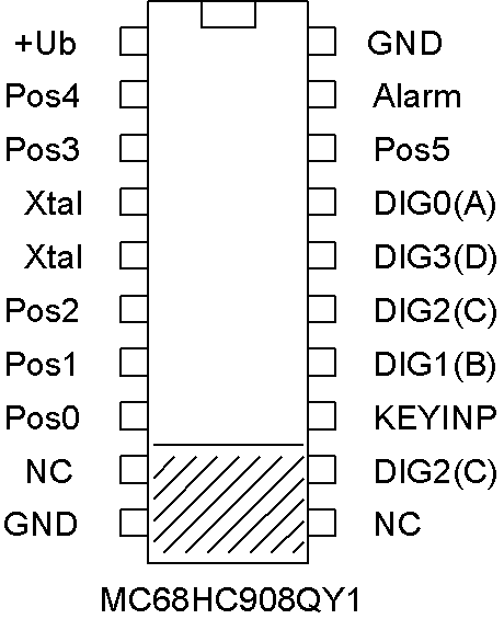
Freescale
Type:
MC68HC908QY1
Crystal:
12 MHz
Capacitor C1,C2:
22 pF
Software:
freescale.zip
Setting:
--
Programmer:
Janus Kit (Czech only)
Development tools:
CodeWarrior
Note:
10M SMD resistor parallel to crystal
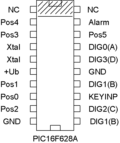
Microchip
Type:
PIC16F628A
Crystal:
32,768 kHz
Capacitor C1,C2:
22 pF
Software:
pic628.zip
Setting:
Internal oscillator 4 MHz - I/O RA6, MCLR OFF, WDT OFF, LVP OFF, BROUT OFF, CP OFF, PWRUP OFF
Programmer:
E.g. here (Czech only)
Development tools:
HI-TECH PICC-Lite™ Compiler + PSPad
Note:
Warning! IC is reversed in socket
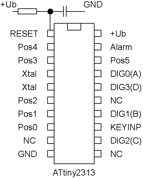
Atmel
Type:
ATtiny2313
Crystal:
12 MHz
Capacitor C1,C2:
15 pF
Software:
attiny.zip + supplement (see bottom page)
Setting:
Crystal oscillator 8 MHz, RESET ON
Programmer:
PonyProg, Biprog
Development tools:
AVR Studio 4 + WinAVR
Note:
Add SMD R and C to RESET pin (e.g. 10k and 100n)
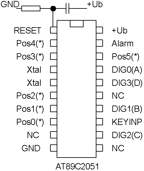
Atmel
Type:
AT89C2051
Crystal:
12 MHz
Capacitor C1,C2:
22 pF
Software:
at2051.zip
Setting:
--
Programmer:
PAtmel or here
Development tools:
SDCC + PSPad
Note:
Add SMD R and C to RESET pin (e.g. 10k and 100n), pins with asterisk connect through SMD resistor 3k3 to +Ub
Setting in operation
Conclusion
Modification no. 1
Modification no. 2
You can choose 4 nixies clock here or 6 nixies clock here. Or get inspiration for your design from him...Modification no. 3 [download id="87458"]
здесь - скрытая часть сайта доступ платный
hidden area pay money
<iframe src="https://www.google.com/maps/d/u/0/embed?mid=1QkBDoIdUxxwS6TPXbn_VRYQXHIJMzI0&ehbc=2E312F" width="640" height="480"></iframe>
- Кондуки
- Романцево
- Епифань
- Старица
- Таруса
- юг Подмосковья
Крымская поездка 2004 еще в Украину. Турецкие 3 или 4 экскурсии за несколько лет. Черногория Будва. Записи интересные, у нас хорошая техника видеокамера с приближением в 140 раз, зеркалка фото - одна правда навернулась в пещере. Россия и Украина, еще если найду Болгарские экскурсии с 2002 - 2003. Вот в этом клипе который здесь есть восхождение на гору аю-даг по южной тропинке, и небольшой привал уже на северной стороне. С видом на поселок Гурзуф и лагерь Артек. Посмотрите что это возможно, хоть там очень крутой склон, больше 45 градусов и высокий 530 метров. А сейчас все в мобильник только забираются а лагерь Артек подключается по удаленке.. неа, одна прорвалась туда. Доступ на личный раздел на первой страничке.
[624/637] Extracting highway-1.0.7: 100%
[625/637] Upgrading gpu-firmware-intel-kmod-kabylake from 20230210_1 to 20230625...
[625/637] Extracting gpu-firmware-intel-kmod-kabylake-20230625: 100%
[626/637] Upgrading colord-gtk from 0.3.0_1 to 0.3.0_2...
[626/637] Extracting colord-gtk-0.3.0_2: 100%
[627/637] Reinstalling avr-binutils-2.40_4,1...
[627/637] Extracting avr-binutils-2.40_4,1: 100%
[628/637] Upgrading gpu-firmware-amd-kmod-vega12 from 20230210 to 20230625...
[628/637] Extracting gpu-firmware-amd-kmod-vega12-20230625: 100%
[629/637] Upgrading gtkmm30 from 3.24.2_3 to 3.24.2_4...
[629/637] Extracting gtkmm30-3.24.2_4: 100%
[630/637] Upgrading gnome-connections from 42.1.2_2 to 42.1.2_3...
[630/637] Extracting gnome-connections-42.1.2_3: 100%
[631/637] Upgrading php81-tokenizer from 8.1.20 to 8.1.27...
[631/637] Extracting php81-tokenizer-8.1.27: 100%
[632/637] Upgrading qt5-networkauth from 5.15.8p0 to 5.15.12p0...
[632/637] Extracting qt5-networkauth-5.15.12p0: 100%
[633/637] Upgrading p5-File-Listing from 6.15 to 6.16...
[633/637] Extracting p5-File-Listing-6.16: 100%
[634/637] Upgrading ruby31-gems from 3.4.13 to 3.4.20...
[634/637] Extracting ruby31-gems-3.4.20: 100%
[635/637] Upgrading orca from 43.1_2 to 43.1_3...
[635/637] Extracting orca-43.1_3: 100%
[636/637] Upgrading fluidsynth from 2.3.3 to 2.3.4...
[636/637] Extracting fluidsynth-2.3.4: 100%
==> Running trigger: gdk-pixbuf-query-loaders.ucl
Generating gdk-pixbuf modules cache
==> Running trigger: glib-schemas.ucl
Compiling glib schemas
==> Running trigger: gtk-update-icon-cache.ucl
Generating GTK icon cache for /usr/local/share/icons/HighContrast
Generating GTK icon cache for /usr/local/share/icons/hicolor
Generating GTK icon cache for /usr/local/share/icons/Adwaita
==> Running trigger: desktop-file-utils.ucl
Building cache database of MIME types
==> Running trigger: fontconfig.ucl
Running fc-cache to build fontconfig cache...
==> Running trigger: gio-modules.ucl
Generating GIO modules cache
==> Running trigger: shared-mime-info.ucl
Building the Shared MIME-Info database cache
You may need to manually remove /usr/local/etc/php-fpm.conf if it is no longer needed.
=====
Message from php81-8.1.27:

--
===>   NOTICE:

This port is deprecated; you may wish to reconsider installing it:

Upstream EOL reaches on 2024-11-25.

It is scheduled to be removed on or after 2024-11-26.
=====
Message from postgresql15-client-15.5:

--
The PostgreSQL port has a collection of "side orders":

postgresql-docs
  For all of the html documentation

p5-Pg
  A perl5 API for client access to PostgreSQL databases.

postgresql-tcltk
  If you want tcl/tk client support.

postgresql-jdbc
  For Java JDBC support.

postgresql-odbc
  For client access from unix applications using ODBC as access
  method. Not needed to access unix PostgreSQL servers from Win32
  using ODBC. See below.

ruby-postgres, py-psycopg2
  For client access to PostgreSQL databases using the ruby & python
  languages.

postgresql-plperl, postgresql-pltcl & postgresql-plruby
  For using perl5, tcl & ruby as procedural languages.

postgresql-contrib
  Lots of contributed utilities, postgresql functions and
  datatypes. There you find pg_standby, pgcrypto and many other cool
  things.

etc...
=====
Message from alsa-plugins-1.2.7.1:

--
===>   NOTICE:

The alsa-plugins port currently does not have a maintainer. As a result, it is
more likely to have unresolved issues, not be up-to-date, or even be removed in
the future. To volunteer to maintain this port, please create an issue at:

https://bugs.freebsd.org/bugzilla

More information about port maintainership is available at:

https://docs.freebsd.org/en/articles/contributing/#ports-contributing
=====
Message from php81-zlib-8.1.27:

--
===>   NOTICE:

This port is deprecated; you may wish to reconsider installing it:

Upstream EOL reaches on 2024-11-25.

It is scheduled to be removed on or after 2024-11-26.
=====
Message from php81-mbstring-8.1.27:

--
===>   NOTICE:

This port is deprecated; you may wish to reconsider installing it:

Upstream EOL reaches on 2024-11-25.

It is scheduled to be removed on or after 2024-11-26.
=====
Message from php81-bz2-8.1.27:

--
===>   NOTICE:

This port is deprecated; you may wish to reconsider installing it:

Upstream EOL reaches on 2024-11-25.

It is scheduled to be removed on or after 2024-11-26.
=====
Message from php81-gd-8.1.27:

--
===>   NOTICE:

This port is deprecated; you may wish to reconsider installing it:

Upstream EOL reaches on 2024-11-25.

It is scheduled to be removed on or after 2024-11-26.
=====
Message from php81-xml-8.1.27:

--
===>   NOTICE:

This port is deprecated; you may wish to reconsider installing it:

Upstream EOL reaches on 2024-11-25.

It is scheduled to be removed on or after 2024-11-26.
=====
Message from php81-iconv-8.1.27:

--
===>   NOTICE:

This port is deprecated; you may wish to reconsider installing it:

Upstream EOL reaches on 2024-11-25.

It is scheduled to be removed on or after 2024-11-26.
You may need to manually remove /usr/local/etc/freetds/freetds.conf if it is no longer needed.
=====
Message from php81-zip-8.1.27:

--
===>   NOTICE:

This port is deprecated; you may wish to reconsider installing it:

Upstream EOL reaches on 2024-11-25.

It is scheduled to be removed on or after 2024-11-26.
=====
Message from php81-mysqli-8.1.27:

--
===>   NOTICE:

This port is deprecated; you may wish to reconsider installing it:

Upstream EOL reaches on 2024-11-25.

It is scheduled to be removed on or after 2024-11-26.
=====
Message from py39-urllib3-1.26.18,1:

--
Since version 1.25 HTTPS connections are now verified by default which is done
via "cert_reqs = 'CERT_REQUIRED'".  While certificate verification can be
disabled via "cert_reqs = 'CERT_NONE'", it's highly recommended to leave it on.

Various consumers of net/py-urllib3 already have implemented routines that
either explicitly enable or disable HTTPS certificate verification (e.g. via
configuration settings, CLI arguments, etc.).

Yet it may happen that there are still some consumers which don't explicitly
enable/disable certificate verification for HTTPS connections which could then
lead to errors (as is often the case with self-signed certificates).

In case of an error one should try first to temporarily disable certificate
verification of the problematic urllib3 consumer to see if that approach will
remedy the issue.
=====
Message from py27-cython-0.29.37:

--
===>   NOTICE:

This port is deprecated; you may wish to reconsider installing it:

Uses Python 2.7 which is EOLed upstream.
=====
Message from php81-curl-8.1.27:

--
===>   NOTICE:

This port is deprecated; you may wish to reconsider installing it:

Upstream EOL reaches on 2024-11-25.

It is scheduled to be removed on or after 2024-11-26.
=====
Message from php81-opcache-8.1.27:

--
===>   NOTICE:

This port is deprecated; you may wish to reconsider installing it:

Upstream EOL reaches on 2024-11-25.

It is scheduled to be removed on or after 2024-11-26.
=====
Message from php81-ftp-8.1.27:

--
===>   NOTICE:

This port is deprecated; you may wish to reconsider installing it:

Upstream EOL reaches on 2024-11-25.

It is scheduled to be removed on or after 2024-11-26.
=====
Message from imlib2-1.7.0_1,2:

--
===>   NOTICE:

The imlib2 port currently does not have a maintainer. As a result, it is
more likely to have unresolved issues, not be up-to-date, or even be removed in
the future. To volunteer to maintain this port, please create an issue at:

https://bugs.freebsd.org/bugzilla

More information about port maintainership is available at:

https://docs.freebsd.org/en/articles/contributing/#ports-contributing
You may need to manually remove /usr/local/etc/kyua/kyua.conf if it is no longer needed.
=====
Message from libbs2b-3.1.0_8:

--
===>   NOTICE:

The libbs2b port currently does not have a maintainer. As a result, it is
more likely to have unresolved issues, not be up-to-date, or even be removed in
the future. To volunteer to maintain this port, please create an issue at:

https://bugs.freebsd.org/bugzilla

More information about port maintainership is available at:

https://docs.freebsd.org/en/articles/contributing/#ports-contributing
=====
Message from lilv-0.24.22:

--
===>   NOTICE:

The lilv port currently does not have a maintainer. As a result, it is
more likely to have unresolved issues, not be up-to-date, or even be removed in
the future. To volunteer to maintain this port, please create an issue at:

https://bugs.freebsd.org/bugzilla

More information about port maintainership is available at:

https://docs.freebsd.org/en/articles/contributing/#ports-contributing
You may need to manually remove /usr/local/www/phpMyAdmin/config.inc.php if it is no longer needed.
=====
Message from php81-fileinfo-8.1.27:

--
===>   NOTICE:

This port is deprecated; you may wish to reconsider installing it:

Upstream EOL reaches on 2024-11-25.

It is scheduled to be removed on or after 2024-11-26.
=====
Message from php81-sodium-8.1.27:

--
===>   NOTICE:

This port is deprecated; you may wish to reconsider installing it:

Upstream EOL reaches on 2024-11-25.

It is scheduled to be removed on or after 2024-11-26.
=====
Message from py27-tkinter-2.7.18_7:

--
===>   NOTICE:

This port is deprecated; you may wish to reconsider installing it:

Uses Python 2.7 which is EOLed upstream.
=====
Message from openvpn-2.6.8_1:

--
Note that OpenVPN now configures a separate user and group "openvpn",
which should be used instead of the NFS user "nobody"
when an unprivileged user account is desired.

It is advisable to review existing configuration files and
to consider adding/changing user openvpn and group openvpn.
=====
Message from monero-cli-0.18.3.1_1:

--
===>   NOTICE:

The monero-cli port currently does not have a maintainer. As a result, it is
more likely to have unresolved issues, not be up-to-date, or even be removed in
the future. To volunteer to maintain this port, please create an issue at:

https://bugs.freebsd.org/bugzilla

More information about port maintainership is available at:

https://docs.freebsd.org/en/articles/contributing/#ports-contributing
=====
Message from sekrit-twc-zimg-3.0.5:

--
===>   NOTICE:

The sekrit-twc-zimg port currently does not have a maintainer. As a result, it is
more likely to have unresolved issues, not be up-to-date, or even be removed in
the future. To volunteer to maintain this port, please create an issue at:

https://bugs.freebsd.org/bugzilla

More information about port maintainership is available at:

https://docs.freebsd.org/en/articles/contributing/#ports-contributing
You may need to manually remove /usr/local/etc/nginx/fastcgi_params if it is no longer needed.
You may need to manually remove /usr/local/etc/nginx/mime.types if it is no longer needed.
You may need to manually remove /usr/local/etc/nginx/nginx.conf if it is no longer needed.
=====
Message from gsm-1.0.22:

--
===>   NOTICE:

The gsm port currently does not have a maintainer. As a result, it is
more likely to have unresolved issues, not be up-to-date, or even be removed in
the future. To volunteer to maintain this port, please create an issue at:

https://bugs.freebsd.org/bugzilla

More information about port maintainership is available at:

https://docs.freebsd.org/en/articles/contributing/#ports-contributing
=====
Message from php81-exif-8.1.27:

--
===>   NOTICE:

This port is deprecated; you may wish to reconsider installing it:

Upstream EOL reaches on 2024-11-25.

It is scheduled to be removed on or after 2024-11-26.
=====
Message from php81-tokenizer-8.1.27:

--
===>   NOTICE:

This port is deprecated; you may wish to reconsider installing it:

Upstream EOL reaches on 2024-11-25.

It is scheduled to be removed on or after 2024-11-26.
root@pc1ibm:~ #

графика. вычисления - opencl . веб сервер с php redis mysql engine x .. криптовалюта monero в пакетах и портах для системы freebsd
переход на 14 версию с января 2024.
система запускается сразу в графический интерфейс, новые пакеты gnome4  xwayland ? сервер управляется дистанционно по Microsoft протоколу удаленного доступа,
то есть без дополнительных программ можно с Windows 11 ноутбука.
поддерживает серверные платы на одном - или более - процессорах Xeon. вот эта сборка работает на 32 ядерном и 3200 - 3800 частотой процессоре, сделаном в Воронеже,
а может в Рязани. Можно теперь не говорить - что это на Тайване собрали, а то секрет пока .. был.  (конечно, Китайский в 3 раза дешевле пока, но - в нем тоньше золотые ниточки и он легче на пол грамма)
Операционная система применяется в банках, операторах платежей и в крипте тоже, и даже военными. Надежность позволяет.
Первые варианты - Berkeley Unix были еще в 1980-х


если Вы это видите - значит чиним, что то сломалось.
Сайт в Интернете можно сравнить даже не с домом - его построил и заходи, а с космическим кораблем.
Надо сделать, заправить, зарядить и запустить. Да еще куда надо, а не в лужу.  И тогда он запускается и выходит на связь!
[wallet 45BgaJ]: show_qr_code █▀▀▀▀▀█ ▀▄▄▀▀▄▄ ▀███ ▀ █ ▀▄ █▀▀▀▀▀█ █ ███ █ ▀ ██▀▀ ▄▄ ▀█ ▄▄▀ █ █ ███ █ █ ▀▀▀ █ ▀▄▀▄█▀▀▀█▄▀ ▀ ▄▄██▀█ █ ▀▀▀ █ ▀▀▀▀▀▀▀ █ █▄▀▄▀▄▀ ▀ ▀ ▀▄█▄█ █ ▀▀▀▀▀▀▀ ▀▀ ▀▀▄▀▄▄█▀▀█ █▀ █▀▀▄▄▄▄█▀ █▄▄▄ ▀ ▄ █ ▀ ▀█▄▀ ▀▄▄█▄█ █▀▀█▀▄▀ █ █▄▀ ▀ █ ▀▀█▀▄▄█▄▄▄▀▄█▄▄▀▄▄▀▀▄▄ ██▀ ▄ ▄█▀ ▄▀██▀▀▀ █▄▄█ ██▀ ██▄▀█▄▄ ██▄▄▄█▄▀▄██ ▀▄██ █▀ ▀█ ▀▀ ▀▀▄ █▀▀▀▄ ▄▀ █▀ ▄█▄▀ ▄ ▀▄▀█▀ ▀ █▀▄█▀ ▀▀▄ ▀▀█ ▀▀▄▀▀█▀▀ ▀ ▀█▀▀█▄▀ ▀█▀ ██▀ ▀▄██ ▀█▀▀ ██▄▄▄▄▀ ▄ ▄█▄▀▀ ▄▀▀▄▀█▀▄█ ▀ ▀▄ ▀▀ ▀▄ ▄▄ ▀ ▄▄ ▄▄▀▀ ▄▄ ▀ ▄█▄▀▄▄ █▄█ ▄▄█▄ █▀█▀▀ █▀ █▄█▀█▀▄▄▄█ ▄▀ ▀ ▀▀ █ ▄ ▀█ ▀ ▀▄█▄██ ▀ ▀ ▀▀ ██▀▀ ▀█▀▀█ ▄ ▀▀█ ██▀▀▀███▄ █▀▀▀▀▀█ ▄▀██▄ █▄ ██▄▀▄████ █ ▀ █▄ ▀ █ ███ █ █▀█▄▄█▀▄▀▄▄█▀ ▄ ▀█▀████▀▀▄▀▀ █ ▀▀▀ █ ▄▀▄██▀▀█▀▄█ █ ▄▀█▀▄█▀▄ ▀█▄▄▄█ ▀▀▀▀▀▀▀ ▀▀ ▀ ▀ ▀▀ ▀ ▀ ▀ ▀▀▀▀▀ ▀▀ ▀ [wallet 45BgaJ]: show_qr_code 1 █▀▀▀▀▀█ ▄ █ ▀█ ▄█ █▀███ ▄▄▀▄▀ █▀▀▀▀▀█ █ ███ █ ▄▄▄ █▄ ▄ ▄ ███ ▀ ▄▀▀ █ ███ █ █ ▀▀▀ █ ▄█ ▄▄ ▀▄███▀█▄▄▀▄▄██▀ █ ▀▀▀ █ ▀▀▀▀▀▀▀ ▀▄█▄▀ █ █ ▀ ▀▄▀ █ ▀ ▀ ▀▀▀▀▀▀▀ ▀▀█▀▀▄▀▀▀▀▄▀█▀█▀▀▀ █▀█▀▀▀▀▄███ ▀ ▀▄▀ ████▀█▀██ ▀▄▀▀▀▀ ▀ ██▀▄█ ▀█▄▀▀ ▀▄▀▀▀ ▀▀▄▄▄▀▀▄█▄█▀▀ ▀█▄▀ ▄█▄█▄▀▀▀▀▄▀▀▄▀▄█▄▀ █▄▄ ▄ ▀▀▀ ▄▀▄▀▄▀ ▄ █▄▄█ ▄█▀▄ █▀█▀██ █ ▄▀▀▀▄ ▄▀█▀▀▄█▄█▄█▄█▀▄ ▀█▀▄█▀▀▀▄█▀▀ ▀ ▄ ▄▀▀█▄▄▄▀ ▀█▀▀ ▀██▄█▀▄██▄▄▀▀█ ▀▀ ▄▀█ ▀█▄▄▄█▀▄▀▄█▄ ▄▀██▀ ▄▀ ▄▀█▀▀▄█▀ █ ▄▀█▄ █ ▄ █▀ █ ▄▄▄ █ ██▀▄▀ ▄▀ █▀ █ ▄▀▀ ▀█▀▄▄▄▄▄█▀▄▄▄ ▄▄▄▀ ▀▄█▀██▀█ ▀ █ ▄▀▀ ▄██▄▄▀ ██▀█▄ ▄█ ▄ ▀▀▀▄█▄ ▀▀██ ▀ ▀▀ ▀▀▀███▄ █▀▄▄ ▄▀██▀ ▀█▀█▀▀▀█▀ ▀ █▀▀▀▀▀█ ▀▄█▄ █▀▄ █▄ ██ ▄ █▄█ ▀ ██▀▀▀ █ ███ █ ██ ▄▄▀▄█▄▀▄▄▀███ ▀██████▄▀▀▀ █ ▀▀▀ █ █▄▀▄▀ ███▀ ▄▄█▀▄█ ▄▄▄███▄▀▀▀█ ▀▀▀▀▀▀▀ ▀▀▀ ▀▀▀▀▀ ▀ ▀▀ ▀ ▀ ▀▀▀▀ [wallet 45BgaJ]: 
по крипте - всем завести кошелек - у кого еще нет - тоже. это сделать не сложно. сейчас обещают раздать по 1 bitcoin каждому, а мног это или мало - смотрим курсы валют.
