табличка перевода децибел милливольт (микроватт) в мощность и напряжение
(будет здесь)
как более привычно ? – например модем выдает 53 dBmv а кабель 75 ом – может более привычно пересчет что это 2.7 ватта и передатчик до +100 градусов нагреется .. непорядок где то сигнал плохо проходит.
скрипт для рассчета mc34063 здесь уже
с десяток схем не перевожу – все понятно
CircuitsRadioOne Watt 2.45 GHz …
One Watt 2.45 GHz Linear Amplifier
04-20-2010
RF Micro Devices RF2126
Schematic:

Reversed PCB pattern:https://search.supplyframe.com/partner/17/searchAd728x90/

BOM:
| Schematic Reference | Value | Description | Package | |
| Capacitors | C1 | 1 µF | electrolytic, 10%, 16V | SMT or leaded |
| C2, C3 | 1000 pF | ceramic, X7R, 50V | 0603 SMT | |
| C4 | 22 pF | Johanson ceramic 5%, 100V | 0504 SMT | |
| C5 | 3.3 pF | ceramic, ±0.25 pF, 50V NP0 | 0402 SMT | |
| C6 | 2 pF | ceramic, ±0.25 pF, 50V NP0 | 0402 SMT | |
| C7 | 1.8 pF | ceramic, ±0.25 pF, 50V NP0 | 0402 SMT | |
| C8 | 1.6 pF | ceramic, ±0.25 pF, 50V NP0 | 0402 SMT | |
| Inductors | L1 | 4.7 nH | 2% | 0603 SMT |
| L2 | 31 ohm @ 100 MHz | ferrite bead, IDC 500 mA | 1206 SMT | |
| Resistors | R1 | 2200 ohm | film, 5% | 0603 SMT |
| R2 | 1000 ohm | film, 5% | 0603 SMT | |
| Integrated Circuits | ICI | RF2126 | RF Micro Devices 1 Watt 2.4 GHz power amplifier | SOP-8 |
| Other | J1, J2 | PCB mount SMA jacks |
Notes:
Part numbers are for reference only. Alternate components may be substituted.
It’s also possible to run the RF2126 at around 6.5 volts for slightly more power output. You could try a 7805 voltage regulator with two silicon diodes (or a red LED) in series with the ground lead (cathode to ground).
Be sure to isolate the ground tab on the 7805 though or it won’t work. You can even just use a plain old 7806 voltage regulator for 6 volts output.

Subscribe e-Newsletter to Stay Informed on New Materials of Our Website!https://googleads.g.doubleclick.net/pagead/ads?client=ca-pub-9426420834445326&output=html&h=90&slotname=4602785022&adk=1461240341&adf=18849865&pi=t.ma~as.4602785022&w=728&lmt=1616150482&rafmt=12&psa=1&format=728×90&url=https%3A%2F%2Fwww.radiolocman.com%2Fshem%2Fschematics.html%3Fdi%3D64364&flash=0&wgl=1&adsid=ChAI8JfRggYQ59397rnn06cbEi8AvbXBBJs89RULVQpZsHHdXwTq5myRu9zlVEViKsvLS4gOWx9bZ-nGvIqUtpKxBw&dt=1616150444588&bpp=33&bdt=6675&idt=1016&shv=r20210316&cbv=r20190131&ptt=9&saldr=aa&abxe=1&cookie=ID%3Da920c3bee270f7ce-22e93d01caba006e%3AT%3D1615930193%3ART%3D1615930193%3AS%3DALNI_MZPpcqSg1Ypf4adzpqKsxHewdCqOQ&prev_fmts=300×250%2C0x0&nras=1&correlator=1453935462496&frm=20&pv=1&ga_vid=433505432.1615930191&ga_sid=1616150449&ga_hid=240936871&ga_fc=0&u_tz=180&u_his=1&u_java=0&u_h=1080&u_w=1920&u_ah=1040&u_aw=1920&u_cd=24&u_nplug=0&u_nmime=0&adx=380&ady=2057&biw=1787&bih=895&scr_x=0&scr_y=0&eid=44739387%2C21069711&oid=3&psts=AGkb-H8CvEqx_zAhoCWJGHW6nmPzRe120qjSozhMM67tTA6eHteuCFy9C3kOLrqn0k0sNyx6bSqddpmf54U&pvsid=1822851021598634&pem=308&ref=https%3A%2F%2Fgoogleads.g.doubleclick.net%2Fpagead%2Fads%3Fclient%3Dca-pub-9426420834445326%26output%3Dhtml%26h%3D426%26slotname%3D9275156383%26adk%3D2543522728%26adf%3D4082262502%26pi%3Dt.ma~as.9275156383%26w%3D728%26cr_col%3D3%26cr_row%3D2%26lmt%3D1616150380%26rafmt%3D9%26psa%3D0%26format%3D728x426%26url%3Dhttps%253A%252F%252Fwww.radiolocman.com%252Fshem%252Fschematics.html%253Fdi%253D33994%26flash%3D0%26crui%3Dpub_control_image_stacked%26wgl%3D1%26adsid%3DChAI8JfRggYQ59397rnn06cbEi8AvbXBBAqWIFygXCE4NZQFxp9qGQfKVC3yXDi8gP8StXi3Yp1Ac96GDXgAIeD_sA%26dt%3D1615930191063%26bpp%3D80%26bdt%3D5762%26idt%3D1766%26shv%3Dr20210310%26cbv%3Dr20190131%26ptt%3D9%26saldr%3Daa%26abxe%3D1%26cookie%3DID%253Da920c3bee270f7ce-22e93d01caba006e%253AT%253D1615930193%253ART%253D1615930193%253AS%253DALNI_MZPpcqSg1Ypf4adzpqKsxHewdCqOQ%26prev_fmts%3D300x250%252C0x0%252C728x90%26nras%3D1%26correlator%3D3397439219820%26frm%3D20%26pv%3D1%26ga_vid%3D433505432.1615930191%26ga_sid%3D1615930193%26ga_hid%3D281646274%26ga_fc%3D0%26u_tz%3D180%26u_his%3D1%26u_java%3D0%26u_h%3D1080%26u_w%3D1920%26u_ah%3D1040%26u_aw%3D1920%26u_cd%3D24%26u_nplug%3D0%26u_nmime%3D0%26adx%3D380%26ady%3D11300%26biw%3D1787%26bih%3D895%26scr_x%3D0%26scr_y%3D7782%26eid%3D42530672%252C44737536%252C21068083%26oid%3D3%26psts%3DAGkb-H85XnX3qltnyZ6LsHHU5AJs4xXnCZZrxCrKcPciNqsHYqsKLyyIoGXfSSd22iZJ8nBSUxiTpOc1F8_BxA%252CAGkb-H81k1ZWEkKTlfGJRq4rhO_RjwOiFZeJtxXfMhrbvcuq-za7aocUzlPHa7MdFijlXiueatpd2LPozjA%26pvsid%3D4102701663334788%26pem%3D308%26ref%3Dhttps%253A%252F%252Fyandex.ru%252F%26rx%3D0%26eae%3D0%26fc%3D896%26brdim%3D55%252C0%252C55%252C0%252C1920%252C0%252C1816%252C1003%252C1804%252C895%26vis%3D1%26rsz%3D%257C%257CeEbr%257C%26abl%3DCS%26pfx%3D0%26fu%3D8320%26bc%3D31%26jar%3D2021-03-11-06%26ifi%3D2%26uci%3Da!2%26btvi%3D2%26fsb%3D1%26xpc%3DJ5l3lqg8b5%26p%3Dhttps%253A%2F%2Fwww.radiolocman.com%26dtd%3DM&rx=0&eae=0&fc=896&brdim=55%2C0%2C55%2C0%2C1920%2C0%2C1816%2C1003%2C1804%2C895&vis=1&rsz=%7C%7CeEbr%7C&abl=CS&pfx=0&fu=8448&bc=31&jar=2021-03-11-06&ifi=1&uci=a!1&btvi=1&fsb=1&xpc=qiBbObsPPm&p=https%3A//www.radiolocman.com&dtd=38344
| You may have to register before you can post comments and get full access to forum. | User Name Remember Me? Password |
| Fragments of discussion: | Full version of discussion » |
- Is this circuit tested? Is it working?
Related publications
- Circuits 300 Watt MOSFET Real HI-FI Power Amplifier
- News OSRAM Opto Semiconductors presents the smallest infrared LED in the 1-Watt class — OSLON SFH 4715S
- News FZLED 22-watt PAR38 LED spotlights with dimming function now available
- News FZLED’s PAR30-03: Long-life 12-Watt Bulbs With Cree LEDs
- Circuits 100 Watt inverter circuit

CircuitsMeasurementMicrocontrollers UsageVery Accurate LC Meter …
Very Accurate LC Meter based on PIC16F84A IC
10-30-2007
This is one of the most accurate and simplest LC inductance / capacitance Meters that one can find, yet one that you can easily build yourself. This LC Meter allows to measure incredibly small inductances starting from 10 nH to 1000 nH, 1 uH to 1000 uH, 1 mH to 100 mH and capacitance from 0.1 pF up to 900 nF. LC Meter’s circuit uses an auto ranging system so that way you do not need to spend time selecting ranges manually. Another neat function is the “Zero Out” switch that will reset the initial inductance / capacitance, making sure that the final readings of the LC Meter are as accurate as possible.https://search.supplyframe.com/partner/17/searchAd728x90/
| LC Meter Part’s List: 2x 1 K 2x 6.8 K 1x 47 K 3x 100 K 1x 10 K POT 2x 10 pF 1x 100 pF 2x 1 nF 2x 10 uF 1x LM7805 1x 16 x 1 LCD Display 1x PIC16F84A IC 1x LM311 IC 1x 4 MHz Crystal 1x 82 uH Inductor 1x 3 V Reed Relay |
| LC Meter’s Technical Specifications: Voltage Supply: 7.5 – 15 V Accuracy: 1% Zero Out Switch Automatic Ranging LC Meter’s Inductance Measurement Ranges: – 10 nH – 1000 nH – 1 uH – 1000 uH – 1 mH – 100 mH LC Meter’s Capacitance Measurement Ranges: – 0.1 pF – 1000 pF – 1 nF – 900 nF |

About LC Meter
This is one of the most accurate and simplest LC inductance / capacitance Meters that one can find, yet one that you can easily build yourself. This LC Meter allows to measure incredibly small inductances starting from 10 nH to 1000 nH, 1 uH to 1000 uH, 1 mH to 100 mH and capacitance from 0.1 pF up to 900 nF. LC Meter’s circuit uses an auto ranging system so that way you do not need to spend time selecting ranges manually. Another neat function is the “Zero Out” switch that will reset the initial inductance / capacitance, making sure that the final readings of the LC Meter are as accurate as possible.

LC Meter Kit with Green Backlight LCD Display

How does LC Meter Work?
To be able to determine the value of an unknown inductor / capacitor we can use the frequency formula given below.
Note that there are three variables that we can work with; f, L and C (f represents a frequency, L inductance and C capacitance). If we know the values of the two variables we may calculate the value of the third variable.
Lets say we want to determine the value of an unknown inductor with X inductance. We plug X inductance into the formula and we also use value of a known capacitor. Using this data we can calculate the frequency. Once we know the frequency we can use the power of the algebra and rewrite the above formula to solve for L (inductance). This time we will use the calculated frequency and a value of a known capacitor to calculate the inductance.
Isn’t this amazing? We just calculated the value of unknown inductor, and we may use the same technique to solve for the unknown capacitance and even frequency.
Applying the Theory to LC Meter’s Hardware
Now let’s use the above theory and apply it to electronics. The LC Meter uses a popular LM311 IC that that functions as a frequency generator and this is exactly what we need. If we want to calculate the value of an unknown inductor we use a know Ccal 1000 pF capacitor and the value of an unknown inductor. LM311 will generate a frequency that we can measure with a frequency meter. Once we have this information we can use the frequency formula to calculate the inductance.
The same thing can be done for calculating the value of a unknown capacitor. This time we don’t know the value a capacitor so instead we use the value of a known inductor to calculate the frequency. Once we have that information we apply the formula to determine the capacitance.
All this sounds great, however if we want to determine the value of a lot of inductors / capacitors then this may become a very time consuming process. Sure, we can write a computer program to do all these calculations, but what if we don’t have an access to a computer or a frequency meter?
That’s were PIC16F84A microchip comes handy. PIC16F84A is like a small computer that can execute HEX programs that are written using an assembly language. PIC16F84A is a very flexible microchip because it has PINs which can be configured as inputs and outputs. Besides that, PIC16F84A IC requires very minimal number of external components like 4 MHz crystal / resonator and few resistors depending on what project we are building. Before we can use PIC16F84A microchip we have to program it with a HEX code which has to be sent from the computer.
In the next step we use the frequency generated by LM311 IC and pass it on to PIC16F84A’s PIN 17. We designate this PIN as an input, as well as all other PINs that are directly connected to switches and jumpers. User can use these inputs to tell the microchip to execute specified set of instructions or perform calculations.
Once the microchip will calculate the unknown inductance or capacitance it will use PINs that are designated as outputs and pass the results on to the 16 character LCD display.
LC Meter’s Switches & Jumpers
SW1 – Zero out the readings.
SW2 – Capacitance / Inductance switch.
J3 – turns on the backlight on LCD displays that have LED backlight.
J1 – used by 16×2 two line character LCD displays.
J2 – displays the initial frequency of the LM311 oscillator which should be around 550 KHz.
Character LCD Display Connections
Most of the character LCD displays have 14 or 16 PINs. The displays that do have a backlight have 16 PINs and displays that do not have a backlight have 14 PINs. The PINs that are highlighted in green in the table below are the ones that PIC16F84A uses to pass the output information represented in bits (0/1).
| PIN Symbol Function States 1 VSS GND – 2 VDD VCC +5V + 3 VO Contrast Adjustment +/- 4 RS Register Select H/L 5 R/W Read / Write H/L 6 E Enable Signal H/L 7 DB0 Data Bit 0 H/L 8 DB1 Data Bit 1 H/L 9 DB2 Data Bit 2 H/L 10 DB3 Data Bit 3 H/L 11 DB4 Data Bit 4 H/L 12 DB5 Data Bit 5 H/L 13 DB6 Data Bit 6 H/L 14 DB7 Data Bit 7 H/L 15 LED Backlight VCC +5V + 16 LED Backlight GND – |
CAUTION: The controller chip that is visible on the back of the LCD display can be damaged with the static energy. Make sure to ground yourself every time you hold it, and handle it by the edges and not the PINs.
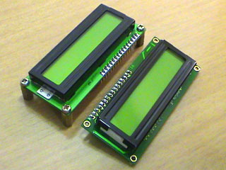 | 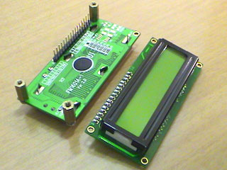 |
| 16 x 1 & 16 x 2 LCD modules with backlight (front) | both LCDs can be used interchangeably |
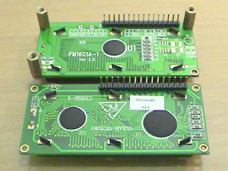 | 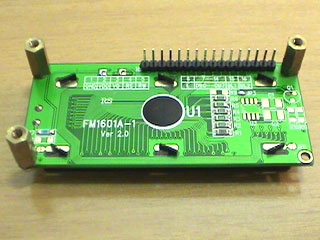 |
| LCD modules (back) | 16 x 1 LCD with pcb standoffs and header pins |
LC Meter’s Enclosure (4″ x 2.5″ x 1″)
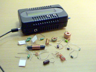 | 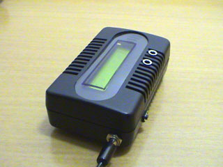 |
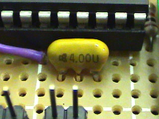
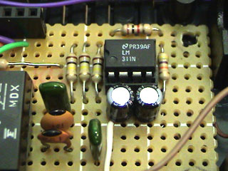
LC Meter’s Construction
 | 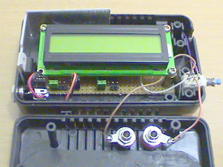 |
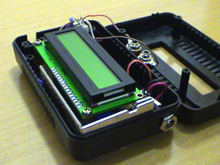 | 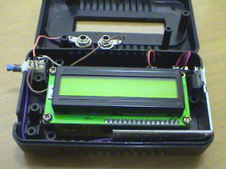 |
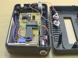 | 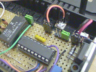 |
 | 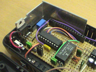 |
 |  |
 |  |
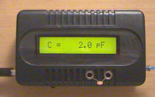
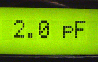
Measuring 2 pF Capacitor
 |  |
Measuring Inductance
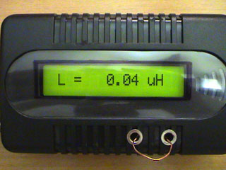 |  |
| 40 nH – small piece of magnet wire | 80 nH – 4 turns of magnet wire |
 | 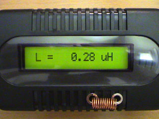 |
| 90 nH coil used in FM transmitter | 280 nH – 10 turns of magnet wire |
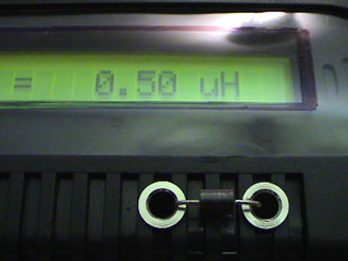 | 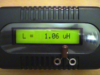 |
| 500 nH wire through choke | 1 uH VK choke |
 |  |
| small RF toroid, 5 turns | medium toroid |
 |  |
| 365 uH | 100 uH choke |
 | 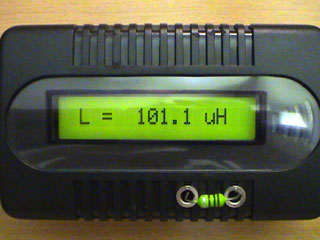 |
| 1 uH inductor | 100 uH inductor |
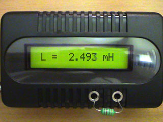 |  |
| 2.2 mH inductor | 18 mH inductor |
Final Recommendations
1nF Ccal is used as a calibration capacitor so make sure that you use a good quality mylar capacitor. Keep the cables between LM311 and the terminals as short as possible to keep the stray capacitance to minimum and ensure the highest accuracy. Also, you have to use a “5V reed relay” because the current passed from PIC16F84A is very small. Reed relays require very minimal amount of current to be switched. I also suggest that you use a 7805 IC to protect the LC Meter, in case you accidentally apply a higher voltage. PIC16F84A will be damaged if you apply voltage higher than 5.5 V.
Before PIC16F84A microcontroller can be used it needs to be flashed with the following HEX program LC_METER.HEX .

Subscribe e-Newsletter to Stay Informed on New Materials of Our Website!https://googleads.g.doubleclick.net/pagead/ads?client=ca-pub-9426420834445326&output=html&h=90&slotname=4602785022&adk=1461240341&adf=18849865&pi=t.ma~as.4602785022&w=728&lmt=1616150371&rafmt=12&psa=0&format=728×90&url=https%3A%2F%2Fwww.radiolocman.com%2Fshem%2Fschematics.html%3Fdi%3D33994&flash=0&wgl=1&adsid=ChAI8JfRggYQ59397rnn06cbEi8AvbXBBAqWIFygXCE4NZQFxp9qGQfKVC3yXDi8gP8StXi3Yp1Ac96GDXgAIeD_sA&dt=1615930191030&bpp=32&bdt=5726&idt=413&shv=r20210310&cbv=r20190131&ptt=9&saldr=aa&abxe=1&cookie=ID%3Da920c3bee270f7ce-22e93d01caba006e%3AT%3D1615930193%3ART%3D1615930193%3AS%3DALNI_MZPpcqSg1Ypf4adzpqKsxHewdCqOQ&prev_fmts=300×250%2C0x0&nras=1&correlator=3397439219820&frm=20&pv=1&ga_vid=433505432.1615930191&ga_sid=1615930193&ga_hid=281646274&ga_fc=0&u_tz=180&u_his=1&u_java=0&u_h=1080&u_w=1920&u_ah=1040&u_aw=1920&u_cd=24&u_nplug=0&u_nmime=0&adx=380&ady=10132&biw=1787&bih=895&scr_x=0&scr_y=7195&eid=42530672%2C44737536%2C21068083&oid=3&psts=AGkb-H85XnX3qltnyZ6LsHHU5AJs4xXnCZZrxCrKcPciNqsHYqsKLyyIoGXfSSd22iZJ8nBSUxiTpOc1F8_BxA&pvsid=4102701663334788&pem=308&ref=https%3A%2F%2Fyandex.ru%2F&rx=0&eae=0&fc=896&brdim=55%2C0%2C55%2C0%2C1920%2C0%2C1816%2C1003%2C1804%2C895&vis=1&rsz=%7C%7CeEbr%7C&abl=CS&pfx=0&fu=8448&bc=31&jar=2021-03-11-06&ifi=1&uci=a!1&btvi=1&fsb=1&xpc=acARSDHeFE&p=https%3A//www.radiolocman.com&dtd=M
| You may have to register before you can post comments and get full access to forum. | User Name Remember Me? Password |
| Fragments of discussion (only 20 last messages): | Full version of discussion » |
- if not difficult someone send in my address PCB, [email]m777r@bk.ru[/email], please!:) Thank You
- hi, please,PCB send my the address [email]matrak81@mynet.com[/email] thank you..
- ples send to me pcb
- Thank you all for the effort is clear and I will try to assemble circuit
- [SIZE=”3″][/SIZE]Thank you very much for the effort and now trying to assemble electronic circuit
- where can i get the pcb?:confused:
- According to numerous requests from users … A lot of information found on one Russian site… [URL=”http://yl2gl.ucoz.net/news/konstrukcija_prostogo_izmeritelja_lc/2011-01-09-62″]Very Accurate LC Meter based on PIC16F84A IC[/URL] See attachments… Good luck!
- Lot of thanks Vadzz…:)
- You’re welcome. 🙂 If that does not make problems, please tell results during construction. For all users: Share your projects and concerns. Thank you.
- i’ll gladly do so..but currently still buying its component..as soon as i started the construction, i’ll post the progress. i also hope to improve the circuit if i’m able to do so.
- [FONT=Courier New]This mail from India ,I make this project .this works very clearly. thank you,[/FONT]
- hallo! I am trying to change .rar files to .hex , but I dont know how? I downloaded this file, but a programmer dont recognize it? Could someone explane where and how I must change the sufix? Thanks! Brko
- Do You know, that *.rar is the archive file? You can unpack this one with [url]http://www.win-rar.ru/download/[/url]
- THANKS
- im cant pcb layot would pcb to pdf tnx
- [URL=”http://uplod.ir/e1k1eldjkeyz/25_PCB_LC_Meter.pdf.htm”]down[/URL] [URL=”http://uplod.ir/m9o8docqh0dy/LC_Meter.pdf.htm”]down1[/URL] [IMG]http://uplod.ir/m9o8docqh0dy/LC_Meter.pdf.htm[/IMG] [IMG]http://uplod.ir/e1k1eldjkeyz/25_PCB_LC_Meter.pdf.htm[/IMG]
- im not part list.send for me partlist
- Can you please tell me what are the specifications of this board? How i can program the PIC? Also how i can design its related circuit? [URL=”http://www.7pcb.com/Prototype-PCB-Assembly.php”]prototype assembly[/URL]
- with the help of programmer PIC controller…
- please help i can’t download any attachment 🙁
Related publications
- Circuits Arduino-based Inductance Meter
- Circuits Power meter is ±1% accurate
- Circuits Arduino based Milliohm Meter with LCD display
- News Highly accurate digital temperature sensors provide unparalleled simplicity for RTD-based and medical designs — TMP117
- Devices Single Phase Energy Meter Reference Design Microchip ARD00280
https://googleads.g.doubleclick.net/pagead/ads?client=ca-pub-9426420834445326&output=html&h=426&slotname=9275156383&adk=2543522728&adf=4082262502&pi=t.ma~as.9275156383&w=728&cr_col=3&cr_row=2&lmt=1616150380&rafmt=9&psa=0&format=728×426&url=https%3A%2F%2Fwww.radiolocman.com%2Fshem%2Fschematics.html%3Fdi%3D33994&flash=0&crui=pub_control_image_stacked&wgl=1&adsid=ChAI8JfRggYQ59397rnn06cbEi8AvbXBBAqWIFygXCE4NZQFxp9qGQfKVC3yXDi8gP8StXi3Yp1Ac96GDXgAIeD_sA&dt=1615930191063&bpp=80&bdt=5762&idt=1766&shv=r20210310&cbv=r20190131&ptt=9&saldr=aa&abxe=1&cookie=ID%3Da920c3bee270f7ce-22e93d01caba006e%3AT%3D1615930193%3ART%3D1615930193%3AS%3DALNI_MZPpcqSg1Ypf4adzpqKsxHewdCqOQ&prev_fmts=300×250%2C0x0%2C728x90&nras=1&correlator=3397439219820&frm=20&pv=1&ga_vid=433505432.1615930191&ga_sid=1615930193&ga_hid=281646274&ga_fc=0&u_tz=180&u_his=1&u_java=0&u_h=1080&u_w=1920&u_ah=1040&u_aw=1920&u_cd=24&u_nplug=0&u_nmime=0&adx=380&ady=11300&biw=1787&bih=895&scr_x=0&scr_y=7782&eid=42530672%2C44737536%2C21068083&oid=3&psts=AGkb-H85XnX3qltnyZ6LsHHU5AJs4xXnCZZrxCrKcPciNqsHYqsKLyyIoGXfSSd22iZJ8nBSUxiTpOc1F8_BxA%2CAGkb-H81k1ZWEkKTlfGJRq4rhO_RjwOiFZeJtxXfMhrbvcuq-za7aocUzlPHa7MdFijlXiueatpd2LPozjA&pvsid=4102701663334788&pem=308&ref=https%3A%2F%2Fyandex.ru%2F&rx=0&eae=0&fc=896&brdim=55%2C0%2C55%2C0%2C1920%2C0%2C1816%2C1003%2C1804%2C895&vis=1&rsz=%7C%7CeEbr%7C&abl=CS&pfx=0&fu=8320&bc=31&jar=2021-03-11-06&ifi=2&uci=a!2&btvi=2&fsb=1&xpc=J5l3lqg8b5&p=https%3A//www.radiolocman.com&dtd=Mhttps://googleads.g.doubleclick.net/pagead/ads?client=ca-pub-9426420834445326&output=html&h=250&slotname=9001955082&adk=37675554&adf=3849154224&pi=t.ma~as.9001955082&w=300&lmt=1615930193&psa=0&format=300×250&url=https%3A%2F%2Fwww.radiolocman.com%2Fshem%2Fschematics.html%3Fdi%3D33994&flash=0&wgl=1&adsid=ChAI8K7BggYQs8fp0t3Gj5sqEi8A6kPaAJQRziKv8dQy8V1qDo_q7PFs-BdqkX6eC8jsJnD6XNcKhFvL8RxyKTMvsQ&dt=1615930191149&bpp=6&bdt=5857&idt=1692&shv=r20210310&cbv=r20190131&ptt=9&saldr=aa&abxe=1&cookie=ID%3Da920c3bee270f7ce-22e93d01caba006e%3AT%3D1615930193%3ART%3D1615930193%3AS%3DALNI_MZPpcqSg1Ypf4adzpqKsxHewdCqOQ&correlator=3397439219820&frm=20&pv=2&ga_vid=433505432.1615930191&ga_sid=1615930193&ga_hid=281646274&ga_fc=0&u_tz=180&u_his=1&u_java=0&u_h=1080&u_w=1920&u_ah=1040&u_aw=1920&u_cd=24&u_nplug=0&u_nmime=0&adx=1122&ady=304&biw=1787&bih=895&scr_x=0&scr_y=0&eid=42530672%2C44737536%2C21068083&oid=3&pvsid=4102701663334788&pem=308&ref=https%3A%2F%2Fyandex.ru%2F&rx=0&eae=0&fc=896&brdim=80%2C231%2C80%2C231%2C1920%2C0%2C1816%2C1003%2C1804%2C895&vis=1&rsz=%7C%7CeoE%7C&abl=CS&pfx=0&fu=8192&bc=31&jar=2021-03-11-06&ifi=3&uci=a!3&fsb=1&xpc=cK4VWhYJvl&p=https%3A//www.radiolocman.com&dtd=2093

Slices
простая схема повышения напряжения step-up
CircuitsMicrocontrollers UsageMeasurement50 MHz frequency counter, …
50 MHz frequency counter, voltage meter & SWR/PWR indicator
07-09-2010
This is a successor of the PIC16C71 4-digit LED f-counter & V-meter. Some hard to find parts used in the previous version, which are out of production for some time, has been omitted. A rather early PIC16C71 has also been replaced by 28-pin device PIC16F876. The later is capable of driving 4 digit LED display in multiplexed mode while measuring frequency, power supply voltage as well as handle two analog inputs to display SWR/PWR signal strength in a bargraph manner. There is no need for external LED display driver chip as well as external data EEPROM since it is already implemented in PIC16F876. Reduction in the number of used chips also results in smaller dimensions of the counter compared to its predecessor.https://search.supplyframe.com/partner/17/searchAd728x90/
Click to enlarge |
| Circuit schematic |
 |  |
| Latest PCB version |
The latest software version (V1.1) supports following functionality:
- Measurement of the frequency up to 50MHz
- Measurement of power supply voltage in the range of 0.0 V … 25.5 V
- Measurement of the input voltage at two analog inputs, simultaneously displayed as bargraph (PWR/SWR or S) indicator. The input sensitivity could be chosen between 0.25V, 0.5V, 1.0V and 2.0V for maximum bargraph indication.
- Power save mode: Automatic display shut-down in case the push-button action or frequency change does not occur for a certain time. Display switches on again after frequency change or push-button action. The available shut-down time periods are 3s, 10s, 30s, 60s, 120s, 180s and 240s. This function can be disabled in set-up menu.
- Programmable frequency offset added or subtracted from measured frequency, settable in the range of 0 to 99,999.9 kHz. This is convenient for use with heterodyne type of RX/TX
- Different display modes: XX.XX MHz, X.XXX MHz, XXX.X kHz
- Display resolution 100 Hz
- Measurement resolution 12,5 Hz
- Hysteresis of displayed value 25 Hz
In operating mode a push-button allows the user to choose between the frequency, bargraph or supply voltage to be displayed. The frequency display mode can also be changed with longer (>1s) push-button pressing. For example if the frequency to be displayed is 14.065.9 MHz the user will see on the four digit display either “065.9”, “4.065” or “14.06”. The default display mode after power-up can be changed in the set-up menu. The set-up menu is entered at power-up while holding the push-button pressed.
The production of Siemens’s (now Infineon’s) miniature 7 seg. LED HDN1077 displays in low current version (suffix O) was abandoned recently. Therefore I’ve designed another display PCBoard which suits the same f-counter base board but uses newer Agilent’s HDSP-U103 miniature 7 seg. LED displays. Their current consumption is even smaller. They need no more than 0,5mA per segment for acceptable brightness. Assuming that during normal operation in average only one half of the segments lights, the average current consumption of the counter is about 20mA. In power-save mode the consumption reduces to less than 10mA which is important in case of battery powered equipment.
The latest software version of the frequency counter is for radio-amateur and non-commercial use downloadable from this page for free. The PIC controller is in-circuit programmable if the MC34064 reset circuit is not soldered to the PCB. The instalation of this IC is strongly recommended after the frequency counter has been built and tested.
 |
| PIC config bits |
Downloads:
HEX code, V1.11 (operates with 4,000 MHz quartz)
Hex code, V1.12 (operates with 4,1943 MHz quartz)

Subscribe e-Newsletter to Stay Informed on New Materials of Our Website!https://googleads.g.doubleclick.net/pagead/ads?client=ca-pub-9426420834445326&output=html&h=90&slotname=4602785022&adk=1461240341&adf=18849865&pi=t.ma~as.4602785022&w=728&lmt=1616151921&rafmt=12&psa=1&format=728×90&url=https%3A%2F%2Fwww.radiolocman.com%2Fshem%2Fschematics.html%3Fdi%3D65713&flash=0&wgl=1&adsid=ChAI8JfRggYQ59397rnn06cbEi8AvbXBBMtp8RHodSCd52DDoAzgApiusTZ5epRAftGXKc2ge_16EVAWN56KUlhTZQ&dt=1616150467712&bpp=113&bdt=1929&idt=575&shv=r20210316&cbv=r20190131&ptt=9&saldr=aa&abxe=1&cookie=ID%3Da920c3bee270f7ce-22e93d01caba006e%3AT%3D1615930193%3ART%3D1615930193%3AS%3DALNI_MZPpcqSg1Ypf4adzpqKsxHewdCqOQ&prev_fmts=300×250%2C0x0&nras=1&correlator=835371806296&frm=20&pv=1&ga_vid=433505432.1615930191&ga_sid=1616150471&ga_hid=676044314&ga_fc=0&u_tz=180&u_his=1&u_java=0&u_h=1080&u_w=1920&u_ah=1040&u_aw=1920&u_cd=24&u_nplug=0&u_nmime=0&adx=380&ady=3357&biw=1787&bih=895&scr_x=0&scr_y=0&eid=21068084%2C44739387&oid=3&psts=AGkb-H9toZpXHCVxSDBKNyiR8xxgDAR6vKprS-Tqn3AIZC3mLaLycz0HlVPEzN63kc_WJvuTIQ3CXv4SgaU&pvsid=1661218268728418&pem=308&ref=https%3A%2F%2Fgoogleads.g.doubleclick.net%2Fpagead%2Fads%3Fclient%3Dca-pub-9426420834445326%26output%3Dhtml%26h%3D426%26slotname%3D9275156383%26adk%3D2543522728%26adf%3D4082262502%26pi%3Dt.ma~as.9275156383%26w%3D728%26cr_col%3D3%26cr_row%3D2%26lmt%3D1616150380%26rafmt%3D9%26psa%3D0%26format%3D728x426%26url%3Dhttps%253A%252F%252Fwww.radiolocman.com%252Fshem%252Fschematics.html%253Fdi%253D33994%26flash%3D0%26crui%3Dpub_control_image_stacked%26wgl%3D1%26adsid%3DChAI8JfRggYQ59397rnn06cbEi8AvbXBBAqWIFygXCE4NZQFxp9qGQfKVC3yXDi8gP8StXi3Yp1Ac96GDXgAIeD_sA%26dt%3D1615930191063%26bpp%3D80%26bdt%3D5762%26idt%3D1766%26shv%3Dr20210310%26cbv%3Dr20190131%26ptt%3D9%26saldr%3Daa%26abxe%3D1%26cookie%3DID%253Da920c3bee270f7ce-22e93d01caba006e%253AT%253D1615930193%253ART%253D1615930193%253AS%253DALNI_MZPpcqSg1Ypf4adzpqKsxHewdCqOQ%26prev_fmts%3D300x250%252C0x0%252C728x90%26nras%3D1%26correlator%3D3397439219820%26frm%3D20%26pv%3D1%26ga_vid%3D433505432.1615930191%26ga_sid%3D1615930193%26ga_hid%3D281646274%26ga_fc%3D0%26u_tz%3D180%26u_his%3D1%26u_java%3D0%26u_h%3D1080%26u_w%3D1920%26u_ah%3D1040%26u_aw%3D1920%26u_cd%3D24%26u_nplug%3D0%26u_nmime%3D0%26adx%3D380%26ady%3D11300%26biw%3D1787%26bih%3D895%26scr_x%3D0%26scr_y%3D7782%26eid%3D42530672%252C44737536%252C21068083%26oid%3D3%26psts%3DAGkb-H85XnX3qltnyZ6LsHHU5AJs4xXnCZZrxCrKcPciNqsHYqsKLyyIoGXfSSd22iZJ8nBSUxiTpOc1F8_BxA%252CAGkb-H81k1ZWEkKTlfGJRq4rhO_RjwOiFZeJtxXfMhrbvcuq-za7aocUzlPHa7MdFijlXiueatpd2LPozjA%26pvsid%3D4102701663334788%26pem%3D308%26ref%3Dhttps%253A%252F%252Fyandex.ru%252F%26rx%3D0%26eae%3D0%26fc%3D896%26brdim%3D55%252C0%252C55%252C0%252C1920%252C0%252C1816%252C1003%252C1804%252C895%26vis%3D1%26rsz%3D%257C%257CeEbr%257C%26abl%3DCS%26pfx%3D0%26fu%3D8320%26bc%3D31%26jar%3D2021-03-11-06%26ifi%3D2%26uci%3Da!2%26btvi%3D2%26fsb%3D1%26xpc%3DJ5l3lqg8b5%26p%3Dhttps%253A%2F%2Fwww.radiolocman.com%26dtd%3DM&rx=0&eae=0&fc=896&brdim=55%2C0%2C55%2C0%2C1920%2C0%2C1816%2C1003%2C1804%2C895&vis=1&rsz=%7C%7CeEbr%7C&abl=CS&pfx=0&fu=8448&bc=31&jar=2021-03-11-06&ifi=1&uci=a!1&btvi=1&fsb=1&xpc=4yjtafVXM0&p=https%3A//www.radiolocman.com&dtd=M
| You may have to register before you can post comments and get full access to forum. | User Name Remember Me? Password |
Related publications
- Circuits 3.5GHZ Frequency Counter
- Circuits 40 MHz Frequency meter on ATmega16
- Circuits Supply Voltage Indicator
- Circuits Digital Mains Voltage Indicator
- Circuits Automotive Voltage Indicator
https://googleads.g.doubleclick.net/pagead/ads?client=ca-pub-9426420834445326&output=html&h=426&slotname=9275156383&adk=2543522728&adf=4082262502&pi=t.ma~as.9275156383&w=728&cr_col=3&cr_row=2&lmt=1616151926&rafmt=9&psa=1&format=728×426&url=https%3A%2F%2Fwww.radiolocman.com%2Fshem%2Fschematics.html%3Fdi%3D65713&flash=0&crui=pub_control_image_stacked&wgl=1&adsid=ChAI8JfRggYQ59397rnn06cbEi8AvbXBBMtp8RHodSCd52DDoAzgApiusTZ5epRAftGXKc2ge_16EVAWN56KUlhTZQ&dt=1616150467826&bpp=75&bdt=2043&idt=1614&shv=r20210316&cbv=r20190131&ptt=9&saldr=aa&abxe=1&cookie=ID%3Da920c3bee270f7ce-22e93d01caba006e%3AT%3D1615930193%3ART%3D1615930193%3AS%3DALNI_MZPpcqSg1Ypf4adzpqKsxHewdCqOQ&prev_fmts=300×250%2C0x0%2C728x90&nras=1&correlator=835371806296&frm=20&pv=1&ga_vid=433505432.1615930191&ga_sid=1616150471&ga_hid=676044314&ga_fc=0&u_tz=180&u_his=1&u_java=0&u_h=1080&u_w=1920&u_ah=1040&u_aw=1920&u_cd=24&u_nplug=0&u_nmime=0&adx=380&ady=3767&biw=1787&bih=895&scr_x=0&scr_y=234&eid=21068084%2C44739387&oid=3&psts=AGkb-H9toZpXHCVxSDBKNyiR8xxgDAR6vKprS-Tqn3AIZC3mLaLycz0HlVPEzN63kc_WJvuTIQ3CXv4SgaU%2CAGkb-H8y2BCB_VEAPZmrBMErbPZ8_UAjArX3YiYZtve4jnlsUgu7bBslTe_qQ7Ax-Mj6CYzE2nRWuJUKdyA&pvsid=1661218268728418&pem=308&ref=https%3A%2F%2Fgoogleads.g.doubleclick.net%2Fpagead%2Fads%3Fclient%3Dca-pub-9426420834445326%26output%3Dhtml%26h%3D426%26slotname%3D9275156383%26adk%3D2543522728%26adf%3D4082262502%26pi%3Dt.ma~as.9275156383%26w%3D728%26cr_col%3D3%26cr_row%3D2%26lmt%3D1616150380%26rafmt%3D9%26psa%3D0%26format%3D728x426%26url%3Dhttps%253A%252F%252Fwww.radiolocman.com%252Fshem%252Fschematics.html%253Fdi%253D33994%26flash%3D0%26crui%3Dpub_control_image_stacked%26wgl%3D1%26adsid%3DChAI8JfRggYQ59397rnn06cbEi8AvbXBBAqWIFygXCE4NZQFxp9qGQfKVC3yXDi8gP8StXi3Yp1Ac96GDXgAIeD_sA%26dt%3D1615930191063%26bpp%3D80%26bdt%3D5762%26idt%3D1766%26shv%3Dr20210310%26cbv%3Dr20190131%26ptt%3D9%26saldr%3Daa%26abxe%3D1%26cookie%3DID%253Da920c3bee270f7ce-22e93d01caba006e%253AT%253D1615930193%253ART%253D1615930193%253AS%253DALNI_MZPpcqSg1Ypf4adzpqKsxHewdCqOQ%26prev_fmts%3D300x250%252C0x0%252C728x90%26nras%3D1%26correlator%3D3397439219820%26frm%3D20%26pv%3D1%26ga_vid%3D433505432.1615930191%26ga_sid%3D1615930193%26ga_hid%3D281646274%26ga_fc%3D0%26u_tz%3D180%26u_his%3D1%26u_java%3D0%26u_h%3D1080%26u_w%3D1920%26u_ah%3D1040%26u_aw%3D1920%26u_cd%3D24%26u_nplug%3D0%26u_nmime%3D0%26adx%3D380%26ady%3D11300%26biw%3D1787%26bih%3D895%26scr_x%3D0%26scr_y%3D7782%26eid%3D42530672%252C44737536%252C21068083%26oid%3D3%26psts%3DAGkb-H85XnX3qltnyZ6LsHHU5AJs4xXnCZZrxCrKcPciNqsHYqsKLyyIoGXfSSd22iZJ8nBSUxiTpOc1F8_BxA%252CAGkb-H81k1ZWEkKTlfGJRq4rhO_RjwOiFZeJtxXfMhrbvcuq-za7aocUzlPHa7MdFijlXiueatpd2LPozjA%26pvsid%3D4102701663334788%26pem%3D308%26ref%3Dhttps%253A%252F%252Fyandex.ru%252F%26rx%3D0%26eae%3D0%26fc%3D896%26brdim%3D55%252C0%252C55%252C0%252C1920%252C0%252C1816%252C1003%252C1804%252C895%26vis%3D1%26rsz%3D%257C%257CeEbr%257C%26abl%3DCS%26pfx%3D0%26fu%3D8320%26bc%3D31%26jar%3D2021-03-11-06%26ifi%3D2%26uci%3Da!2%26btvi%3D2%26fsb%3D1%26xpc%3DJ5l3lqg8b5%26p%3Dhttps%253A%2F%2Fwww.radiolocman.com%26dtd%3DM&rx=0&eae=0&fc=896&brdim=55%2C0%2C55%2C0%2C1920%2C0%2C1816%2C1003%2C1804%2C895&vis=1&rsz=%7C%7CeEbr%7C&abl=CS&pfx=0&fu=8320&bc=31&jar=2021-03-11-06&ifi=2&uci=a!2&btvi=2&fsb=1&xpc=MrVAFhcIUj&p=https%3A//www.radiolocman.com&dtd=M
прошивка во вложении s lc-meter
Very Accurate LC Meter based on PIC16F84A IC.
23:50 ч. Публикувано от Unknown
Етикети: измервания, PIC
Список деталей:
2x 1K
2x 6.8K
1x 47K
3x 100K
1x 10K переменный резистор
2x 22pF
1x 56pF
1x 100pF
2x 1nF
2x 10uF
1x 16×1 LCD дисплей
1x PIC16F84A IC
1x LM311 IC
1x 4 MHz Crystal
1x 82uH Катушка
1x 3V Геркон
Программу можно закачать тут.
Технические спецификации:
Напряжение питания: 5V
Точность: 1%
Система сброса
Автоматический выбор диапазона
Область измерения индуктивности:
– 10nH – 1000nH
– 1uH – 1000uH
– 1mH – 100mH
Область измерения емкости:
– 0.1pF – 1000pF
– 1nF – 300nF

| Об LC – метре —————————————————————————— Это самый точный и простой LC метр который вы сможете найти. Он позволяет вам измерять очень маленькие индуктивности, начиная от 10nH до 1000nH, от 1uH до 1000uH и от 1mH до 100mH, и емкости от 0.1pF вплоть до 300nF. Прибор использует систему автоматического выбора диапазона, так что вам не придется тратить время для выбора его вручную. Еще одна полезная функция это переключатель моментального “Сброса в ноль”, который сбросит прежнее значение индуктивности / емкости, гарантируя что последние данные точны, насколько это возможно. Как это работает? —————————————————————————— Чтобы определить значение неизвестной катушки или конденсатора, мы можем использовать формулу частоты, данную ниже. Замечу, что есть три переменные, с которыми мы можем работать: f, L и C (f частота, L индуктивность и C емкость). Если нам известны значения двух переменных, мы можем посчитать значение третьей. Допустим, что мы хотим определить значение катушки, с индуктивностью X. Мы подставляем индуктивность X в формулу, и используем известное значение емкости конденсатора. Используя эти данные мы можем рассчитать частоту. Если нам известна частота, мы можем использовать силу алгебры и переписать верхнюю формулу чтобы найти L (индуктивность). В этом случае мы используем рассчитанную частоту, и известное значение конденсатора, чтобы рассчитать индуктивность. Не изумительно ли это? Мы только что рассчитали неизвестное значение катушки, и мы можем использовать ту же технику для расчета неизвестного конденсатора и даже частоты. Воплощение теории в оборудовании. ——————————————————————————— Теперь давайте используем теорию, изложенную выше и применим ее в электронике. LC – метр использует популярную микросхему LM311, функционирующую как генератор частоты, что нам и надо. Если мы хотим рассчитать неизвестное значение катушки мы используем конденсатор Ccal с емкостью 1000pF и значение неизвестной катушки. LM311 сгенерирует частоту, которую мы можем измерить с помощью частотомера. Получив эту информацию мы сможем использовать формулу частоты для расчета индуктивности. Тоже самое может быть сделано для расчета неизвестного конденсатора. В этот раз мы не знаем значение конденсатора, так что вместо него используем известное значение катушки, для расчета частоты. Когда получим данные, обратимся к формуле, для определения емкости. Звучит хорошо, однако если мы хотим определить значение многих катушек / конденсаторов, тогда это может стать очень длительным процессом. Конечно, мы можем написать компьютерную программу, но что если у нас нет доступа к компьютеру или частотомера. Вот почему полезным становится PIC16F84A. PIC16F84A как небольшой компьютер, который может выполнять HEX программы, написанный с использованием ассемблера. PIC16F84A легко приспосабливаемый микрочип, так как имеет выводы, которые могут быть настроены как на вход так и на выход. Кроме того PIC16F84A требует очень небольшого числа внешних компонентов таких как 4MHz кристалл / резонатор и нескольких резисторов, зависящих от того каким мы занимаемся проектом. Перед использованием PIC16F84A его нужно запрограммировать HEX, который должен быть послан с компьютера. На следующем этапе мы используем частоту, сгенерированную микросхемой LM311, и отправляем ее на ножку 17 микроконтроллера. Мы назначили эту ножку для входа, заодно и все другие напрямую подключили к переключателем и перемычкам. Пользователь может использовать эти входы, чтобы приказать контроллеру выполнить определенный набор инструкций или расчеты. После расчета неизвестной частоты или емкости микроконтроллер использует ножки, определенные на выход и передаст результаты на 16 – ти символьный дисплей. Переключатели / Перемычки ————————————————————————————– SW1 – Zero out the readings. SW2 – Переключатель индуктивность / емкость. J3 – Включает подсветку LED дисплея, у LED дисплеев имеющих ее J1 – использован 16 – ти символьный двухстрочный LCD дисплей. J2 – показывает исходную частоту генератора LM311, которая должна быть в районе 550KHz. Соединение символьного LCD дисплея. ————————————————————————————– Большинство символьных LCD дисплеев имеют 14 или 16 ножек. Дисплеи у которых есть подсветка имеют 16 ножек, а у которых нет – 14 ножек. Ножки, окрашенные в зеленый в таблице внизу это те которые PIC16F84A использует для вывода информации, представленной в битах (0/1). PIN Symbol Function States 1 VSS GND – 2 VDD VCC +5V + 3 VO Contrast Adjustment +/- 4 RS Register Select H/L 5 R/W Read / Write H/L 6 E Enable Signal H/L 7 DB0 Data Bit 0 H/L 8 DB1 Data Bit 1 H/L 9 DB2 Data Bit 2 H/L 10 DB3 Data Bit 3 H/L 11 DB4 Data Bit 4 H/L 12 DB5 Data Bit 5 H/L 13 DB6 Data Bit 6 H/L 14 DB7 Data Bit 7 H/L 15 LED Backlight VCC +5V + 16 LED Backlight GND – ВНИМАНИЕ: Чип контроллера, который видно сзади LCD дисплея может быть поврежден статическим разрядом. Позаботьтесь о своем заземлении , каждый раз кода берете его, и держите его за края, а не за ножки. Последние рекомендации —————————————————————————————- 1nF Ccal используется как калибровочный конденсатор, так что убедитесь что используете качественный конденсатор на майларовой плёнке. Сделайте проводки между LM311 и клеммами как можно короче, чтобы свести паразитную ёмкость к минимуму и гарантировать высочайшую точность. Вам также придется использовать “5V геркон”, так как ток от PIC16F84A очень мал. Герконам нужен очень маленький ток чтобы переключиться. Я также советую использовать микросхему 7805 для защиты LC – метра, в случае если вы случайно подадите большее напряжение. PIC16F84A будет поврежден если вы подадите напряжение выше 5.5V. Прошивка контроллера. За перевод благодарим Night watcher h  |
LC Meter Kit with Green Backlight LCD Display
16×1& 16×2 LCD modules with backlight (front) both LCDs can be used interchangeably LCD modules (back) 16×1 LCD with pcb standoffs and header pins |
LC Meter’s Enclosure (4″x2.5″x1″)
LC Meter’s Construction
Measuring 2pF Capacitor
Measuring Inductance
https://googleads.g.doubleclick.net/pagead/ads?client=ca-pub-0546845799232010&output=html&h=60&slotname=4214979175&adk=1742221364&adf=1069214578&pi=t.ma~as.4214979175&w=468&lmt=1582928004&url=http%3A%2F%2Felectro-admin.blogspot.com%2F2008%2F10%2Fvery-accurate-lc-meter-based-on.html&flash=0&host=pub-1556223355139109&h_ch=00000&wgl=1&adsid=ChAI8JfRggYQ59397rnn06cbEi8AvbXBBBfl0v7Xqje5lcX7Ex94xsgkM_GWv57yZiCoTcWyFStjtfMgCafJxtkrFg&dt=1616152394556&bpp=20&bdt=236050&idt=20&shv=r20210316&cbv=r20190131&ptt=5&saldr=sa&abxe=1&prev_fmts=0x0&prev_slotnames=4214979175&nras=1&correlator=6229615323296&pv_h_ch=00000&frm=20&pv=1&ga_vid=1982450271.1616152390&ga_sid=1616152390&ga_hid=355585433&ga_fc=0&u_tz=180&u_his=1&u_java=0&u_h=1080&u_w=1920&u_ah=1040&u_aw=1920&u_cd=24&u_nplug=0&u_nmime=0&adx=496&ady=9834&biw=1787&bih=895&scr_x=0&scr_y=7405&eid=42530672%2C44737562%2C44739387&oid=3&pvsid=1868531737139930&pem=755&ref=https%3A%2F%2Fyandex.ru%2F&rx=0&eae=0&fc=896&brdim=55%2C0%2C55%2C0%2C1920%2C0%2C1816%2C1003%2C1804%2C895&vis=1&rsz=%7C%7CeEbr%7C&abl=CS&pfx=0&fu=8192&bc=23&jar=2021-02-21-12&ifi=2&uci=a!2&btvi=1&fsb=1&xpc=zs9cTB6OxE&p=http%3A//electro-admin.blogspot.com&dtd=75605
0 коментара:
Enews And Updates
Labels
- аудио (1)
- измервания (11)
- изработка (16)
- индукционен баланс (28)
- лаборатория (6)
- магнитометри (5)
- металдетектор (25)
- модификация (1)
- пулс-индукционен (1)
- руска (33)
- схема (3)
- теория (16)
- търсеща глава (12)
- PIC (8)
Advertisement
Lamqta.com – Сайт за здравето, домът и нещата от живота

Blog Archive
- ▼ 2008 (49)
- ▼ Октомври (49)
- Адаптер за измерване на индуктивност
- Изработка на SUBWOOFER
- Честотомер, измервател на капацитет и индуктивност…
- USB осцилоскоп със PIC18F2550
- Измерване на съпротивление, капацитет и индуктивно…
- калкулатор за брой навивки за многослойна намотка
- Very Accurate LC Meter based on PIC16F84A IC.
- Генератор на правоъгълни и синусоидални колебания
- Пет начина за получаване на необходимата температу…
- Универсален нискочестотен генератор
- LC – приставка към цифровия волтметър
- A Surprisingly Accurate Digital LC Meter
- LC-метър със PIC16F84
- Manufacturer’s Specifications of the L/C Meter IIB
- LC-meter FREE project
- Изработка на металотърсач Magnum
- Изработка на металотърсач “ГРОЗА-3” (THUNDER – III…
- Изработка на металотърсач “ГРОЗА-3” (THUNDER – III…
- Изработка на металотърсач “ГРОЗА-3” (THUNDER – III…
- Пресмятане на индуктивност на бобина
- Изработка на металотърсач “ГРОЗА-3” (THUNDER – III…
- Как да направим търсеща глава?
- Търсеща глава – ръководство за изработка!
- Търсеща глава – «Кольцо»!
- Технология за изработка на датчик за Anker – 50 М
- ANKER-50M
- Настройка металлоискателя “Anker-50”
- Основные технические характеристики металлоискател…
- О разработке протонных магнитометров. Часть 5.
- О разработке протонных магнитометров. Часть 4.
- О разработке протонных магнитометров. Часть 3.
- О разработке протонных магнитометров. Часть 2.
- О разработке протонных магнитометров. Часть 1.
- Немного о разном.
- Фазы в контурах.
- Последовательный контур. Резонанс напряжений.
- Параллельный контур. Резонанс токов.
- IB металлодетекторы. Часть 3.
- IB металлодетекторы. Часть 2.
- IB металлодетекторы. Часть 1.
- Альтернативные датчики для металлоискателя Кощей-…
- Альтернативные датчики для металлоискателя Кощей-1…
- Альтернативные датчики для металлоискателя Кощей-1…
- Альтернативные датчики для металлоискателя Кощей-1…
- Альтернативные датчики для металлоискателя Кощей-1…
- Индукционный двухчастотный металлоискатель КОЩЕЙ-18М
- Металотърсач (Beachcomber90VLF)
- Модификация Whites Classic – Classic MOD ver 0.2
- CLONE-PI -M
- ▼ Октомври (49)
- August 2025
- June 2025
- April 2025
- March 2025
- January 2025
- November 2024
- August 2024
- June 2024
- February 2024
- January 2024
- December 2023
- September 2023
- August 2023
- June 2023
- May 2023
- April 2023
- January 2023
- November 2022
- October 2022
- September 2022
- August 2022
- July 2022
- April 2022
- January 2022
- December 2021
- November 2021
- September 2021
- May 2021
- December 2020
- August 2020
- July 2020
- June 2020
- February 2020
- January 2020
- November 2019
- October 2019
- September 2019
- August 2019
- June 2019
- May 2019
- April 2019
- February 2019
- October 2018
- September 2018
- August 2018
- July 2018
- April 2018
- March 2018
- February 2018
- January 2018
- December 2017
- October 2017
- September 2017
- August 2017
- July 2017
- May 2017
- March 2017
- January 2017
- August 2016
- July 2016
- June 2016
- March 2016
- December 2015
- November 2015
- July 2015
- April 2015
- March 2015
- January 2015
- December 2014
- October 2014
- September 2014
- August 2014
- July 2014
- March 2014
- January 2014
- December 2013
- November 2013
- April 2013
- March 2013
- December 2012
- March 2012
- August 2011
- December 2010
- February 2010
- September 2009
- November 2005
- April 2004
- March 2004
- February 2004
- Суздаль
- Таруса
- Покатушка по окрестностям
- Албания 2018. Часть 3: Болгария
- Victoria HDD восстановление данных

